The place where random ideas get written down and lost in time.
2020-11-25 - Blinking LED - Astable transistor/555 approach
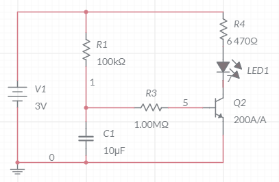
Category DEVAnother surely doomed attempt using an RC and a transistor. As expected, it did not work.
Although it is inherently flawed, I’ll put it here:
Transistor is a 2N3904.
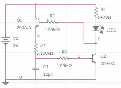
This obviously does create a delay starting the LED. Then there’s nothing to stop it. The futile idea was to add a second transistor between “ground” and the battery minus side to cut the circuit. Problem is that there’s nothing here that would generate something suitable to trigger it. Something like this:
Closer but obviously very wrong. That top Q3 transistor has to be at the “ground” level and mirror Q2, which I tried in the simulator but I screwed it up and didn’t want to get the embarrassingly bad schema. Anyhow, two Q2/Q3 in symmetry… which seems familiar… if only that had been solved...
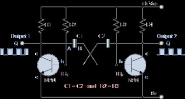
What I want is an “astable multivibrator”: https://www.electronics-tutorials.ws/waveforms/astable.html
Let’s compute some values.
- Desired: t1=0.5s, t2=2s (just making that up).
- T1 = 0.69 C1 R3
- T2 = 0.69 C2 R2
- C1 = 10u ⇒ R3 = 0.5 / 0.69 / 10e-6 = 72.4k Ω
- Rounding up: R3 = 100k Ω ⇒ t1 = 0.69 s
- C2 = 10u ⇒ R2 = 2 / 0.69 / 10e-6 = 188k Ω
- Rounding up: R2 = 220k Ω ⇒ t2 = 2.2s
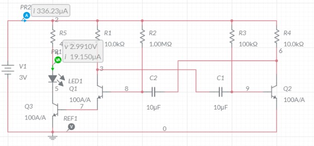
Of note, to control the LED, we need a 3rd transistor on the emitter of TR1/TR2 as shown above. That’s interesting as I’d have driven it out of the Q output using a high value resistor.
So I built that circuit using 3 transistors 2N3904. R1 = R4 = 10k Ω, R2 = 220k Ω, R3 = 100k Ω, C1 = C2 = 10uF. For the LED part, I have a 1.88 Vf red LED with a 470 Ω resistor.
For a better timing, I changed R2 to 1M Ω ⇒ t2 = 6.9 s.
That would bring t1+t2 to around 8 seconds. I measured around 8~9 s for t1+t2.
Duty cycle is t1 / t1+t2 = 9.1% LED on.
I am failing to measure actual current usage with a multimeter.
With the simulator in National Instruments Multisim:
I have no idea what kind of transistor they are modeling here. Doesn’t look like a 2N3904.
This gives me A=5 mA when the LED is on, and 0.3 mA when the LED is off.
Combined with the duty cycle: (0.69s*5mA + 6.9s*0.3mA) / 7.59s = 0.72 mA/s = 2618 mA/h.
Technically a bit lower as the LED is not fully at 5 mA while on; it turns on progressively. But even if the on cycle was half current at 2.5 mA, it would be (0.69s*2.5mA + 6.9s*0.3mA) / 7.59s * 3600 = 1800 mA/h.
A typical AA alkaline battery has a capacity of 2500 mAh. Since I use 2 of them, I’d expect this to last 2~3 hours before the batteries are depleted.
Update: Tried this and it lasted at least 3 days with little impact on battery. That 300 uA quiescent current seems like a lot.
555 timer
The obvious choice is to go with a 555 timer. I realize I don’t have any around.
Now there are plenty of schematics built around the 555. What I want is one giving me a configurable square wave. Like this one: https://www.electronics-tutorials.ws/waveforms/555_oscillator.html
So let’s compute the RC values needed.
- Desired: t2=0.5s, t1=2s (just making that up).
- T1 = 0.693 (R1 + R2) C1
- T2 = 0.693 R2 C
- C=10u ⇒ R2=0.5 / 0.693 / 10e-6 = 72k Ω
- Rounding up: R2 = 100k Ω ⇒ t2 = 0.693 s
- R1= 2 / 0.693 / 10e-6 - 100k = 188.6k Ω
- Rounding up: R1 = 220k Ω ⇒ t1 = 2.2 s
- Duty cycle is (R1+R2)/(R1+2 R2) = 76%
There are variations to improve on the duty cycle using diodes.
As a demonstration, that was successful using the transistor version of the astable.
I’d see some value in having a few 555s around, as it makes this kind of project a breeze, so that’s something to look into.
I do realize I do not know how to estimate battery longevity.
Side note: There are cheap “10x 555” deals for $1 on ebay from China of course.
There are also packages with e.g. “120 pcs” of “IC assorted” components on Amazon. Not sure they are interesting. Let’s take one listing and understand what the “ICs” are:
- LM324 - Quad AmOp, up to 32 V, 1.3 W.
- LM339 - Quad Differential Voltage Comparator, up to 30 V, 20 mA out.
- ULN2003AN - Darlington Array (aka 8x 500 mA output drivers). I have 4x, never used.
- ULN2803APG - Same, from Toshiba.
- LM358P - Dual AmOp,up to 30 V, 20 mA out.
- LM386 - Low Voltage Audio Amp, in 4-12 V, gain 20-200. 300 mA out.
- LM393 - Dual Comparators, up to 30 V.
- NE5532P - Dual Low-Noise AmOp.
- NE555P - “Precision” Timer.
- UA741CN - General Purpose AmOp, the typical 741...
- JRC4558D - Aka RC4558, General Purpose AmpOp.
- PC817 - General Purpose Photocoupler. I have a set of 10x of similar ones.
So bottom line here we have 1 type of timer, 1 type of optocoupler, 6 types of AmOp, 2 types of comparators, and 2 types of darlington drivers. I don’t see myself using many of these. I have so far used 1 of the optos I have (and just for testing, although I was supposed to need 10x for a Randall project), and I never used the 2003 drivers I got (that was to drive mechanical relays for the sprinkler project which I never started), and here I would be using maybe 1x 555 timer for a quick test (for a project I already decided I’m unlikely to finalize using a 555).


