The Randall Museum in San Francisco hosts a large HO-scale model model railroad. Created by the Golden Gate Model Railroad Club starting in 1961, the layout was donated to the Museum in 2015. Since then I have started automatizing trains running on the layout. I am also the model railroad maintainer. This blog describes various updates on the Randall project and I maintain a separate blog for all my electronics not directly related to Randall.
2018-11-03 - Stockton Passenger Station Power
Category RandallSo here’s an interesting problem: where does the power from the Stockton Passenger Station come from?
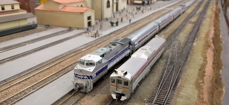
On this picture, the two rightmost tracks are mainline. Everything on the left is the Stockton Passenger Station. The Budd RDC is on the mainline whereas the Amtrak is on a passenger station track.
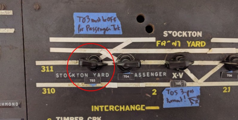
And then when the T03 turnout is set in reverse position on the mainline, the station loses power… Why?!
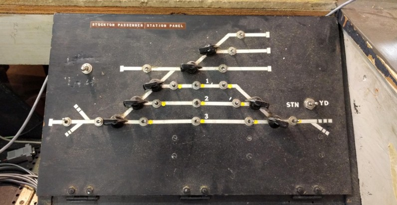
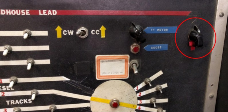
The corresponding panel for the station and its inner workings below. Each block power selector has two choices: yellow dot on the right for DCC mode and left side for DC, from what I was told. There’s no DC left on the layout so that side goes to… I don’t know where. So where does the DCC come from? Which booster? A quick test shows it comes from the Stockton Yard power district.
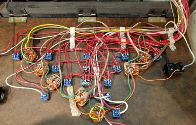
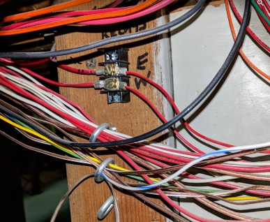
Fairly neat cabling underneath, I’d rather say. Power comes from a terminal block labelled “E / W”. The “E” one matches the yellow dot “DCC” position:
Writing on the support is “Relays E / W”. East / West makes sense. East is on the right side of the station, and West is on the left side.
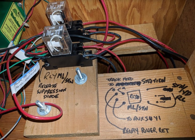
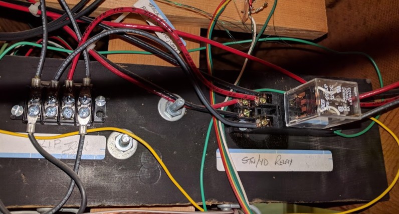
Tracing the “E” power lead brings me to an interesting contraption of relays under the Stockton Yard:
A few interesting things here:
- The “E” power lead is controlled by that double relay (top picture). The output is neatly labeled “Power to STN Panel Eastside”. So at least I got the right lead wire.
- Schema indicates this is controlled by the “STN/YD Relay” which can be found in the middle picture.
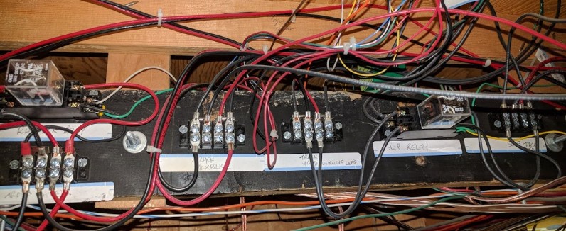
- Power & control of that relay then goes into adjacent terminal blocks.
- All these match the extensive and very well drawn schematics left by Mr. Perry.
Naming:
- STN/YD is obviously Stockton Yard.
- ML/STN is Mainline / Stockton.
- “SLIP” track (or block?) seems to denote the special diamond/turnout of the T03/T04 4-way turnout.
I looked at where the “W” power lead goes. As expected, it leads to another relay somewhere under the Rodgers section of the layout..
At that point, it’s clear Mr. Perry spent quite some time designing and installing and wiring all the stuff. The question is why. What problem does this solve? How does it solve it?
One of these relays is controlled directly or indirectly by the T03 turnout (I’m guessing actual connection is via an output of the corresponding tortoise; I was unable to actually trace that wire, yet it’s clearly labeled on the schematics I have now). In the double-relay above, one of the relays is controlled by a turnout toggle that connects the roundhouse lead to the Stockton tracks, also as indicated in the schematics:
Due to the DC nature of the layout, a lot of the power management was obviously originally driven by the need to separate power districts and have interchange tracks with power source selectors -- in that case, the station can be powered by the mainline, the Stockton Yard, or the Roundhouse Lead on the East side, or from the mainline or SIA/Branchline on the West side, depending on whether the West or East access are used. And when using a DC throttle, it makes sense to properly power all the interexchange tracks. So maybe that’s one rationale here. Or maybe there’s something else going on. I’d really want to understand the purpose of all this before I make any changes to it (if any are needed at all).
In the end, the objective is to make sure the station remained powered even when switching happens in the yard and the T03 turnout is used. The automation needs the station to be powered at all time -- otherwise the block sensors can’t identify the trains located there. Right now anyone switching in the Stockton Yard can render the automation inoperative just by setting T03 in reverse.
The other thing to remember is that I did remove all the DC equipment. In DC mode, most of the layout was designed to power from a “cab 1” vs “cab 2” (and sometimes a local yard throttle), and the DCC has essentially been retrofitted to “cab 1” (I’m simplifying here). That leaves the other cab totally unpowered. So one question is why not wire both cab 1 and cab 2 together, this way things would work seamlessly. That however seems a bit of a brute force technique, and one reason I want to avoid doing that is to inadvertently connect two or more boosters together (been there, done that). And that’s a concern here -- I could of course force the relays in a position that would power the track I want all the time, but doing so could also inadvertently bridge too circuits which are supposed to stay isolated.
Instead my philosophy has been to try to understand the rationale behind the current setup when something doesn’t work as expected.
