The Randall Museum in San Francisco hosts a large HO-scale model railroad. Created by the Golden Gate Model Railroad Club starting in 1961, the layout was donated to the Museum in 2015. Since then I have started automatizing trains running on the layout. I am also the model railroad maintainer. This blog describes various updates on the Randall Museum Model Railroad and I maintain a separate tech blog for all my electronics & software not directly related to Randall.
2019-02-13 - Randall Repairs: Turnout T320
Category RandallAffected |
Turnout T320 (crossover from B321 to B320). |
Description |
The point on the turnout on B321 was not throwing completely in Normal position, thus sometimes trying to diverge engines & shorting. |
Summary Fix |
Temporarily fixed by forcing turnout in Normal direction & disconnected control wires from Switch-8 to prevent activation. Needs more work. |
Description of Issue
T320 is a crossover that brings trains from block B321 to B320 in our normal running direction.
After working flawlessly for 2 weeks, the automated trains started stopping and shorting on this turnout last week.
Issue 1: Turnout Toggle / Selector
One minor issue that has been present since 2017 concerns the rotary turnout toggle on the panel. These toggles normally have a little tab that sticks into the wood panel to prevent them from turning. In this case the wood has softened and the rotary toggle turns freely. Its visual orientation on the panel does not bear any indication of the actual position of the toggle.
This panel is nowadays rarely used and since this turnout has DCC control, it can be more easily thrown using the ACCY function of the NCE ProCab controllers. Consequently, the “loose” toggle issue has not been fixed yet. It is recorded on the task list as a low-priority item.
Issue 2: Misaligned Point
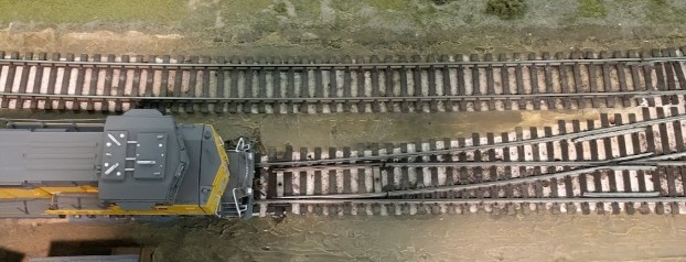
Starting last week, automation trains started shorting on the turnout. Examination shown that the West turnout of the cross-over, located on B321, had the point in the diverging position. The East turnout of the cross-over was in the normal/straight position. When the train automation starts, it always aligns this turnout to normal/straight.
Here’s a photo of the West side of T320, which is supposed to be aligned for normal:
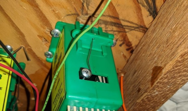
And in fact checking the Tortoise under the layout shows that, as far as the tortoise is concerned, the turnout is aligned to normal:
Note: both pictures are taken from the “same” side. The Tortoise screw is on the left, and the throwbar wire should pivot and throw the point to the right (towards the top in the above-the-rail picture).
When trying to move the point manually, I noticed it always sprung back to the incorrect position, regardless of the position of the Tortoise throwbar wire. There could simply be some debris under the throw-bar or the point that prevent it from closing properly in the normal position.
Finally, I noticed the T320 toggle on the panel was in the diverging/thrown position. I don’t know how long it has been in that position. The toggle is connected to a Switch-8. The way the Switch-8 works, when the layout is powered on it always aligns the turnouts to the panel’s toggle positions. Then the automation starts and always set that turnout to normal. In all likelihood, this scheme means that every day, when the layout is powered, the T320 would be thrown to diverging and then a few minutes later re-aligned to normal, every single day.
Description of Fix
The proper fix is to adjust the point so that it can close properly, and to replace the Tortoise throwbar wire. A few articles out there (example here) indicate sometimes the throwbar wire provided with the Tortoise is not strong enough. However before getting there, I wanted to provide a quick fix to be able to let the daily automation continue and I wanted to isolate the problem so a temporary fix was set in place.
1- Temporary Fix
The temporary fix is to disable the turnout and force it in “normal” position. This way we’ll quickly know whether this is the core of the issue.
To force the turnout in normal position, 3 changes were made.
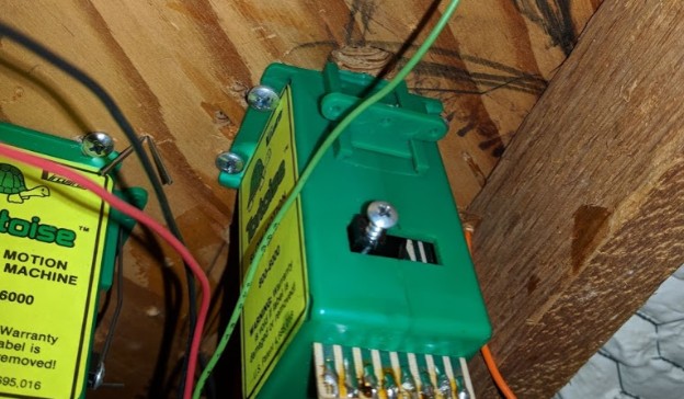
Tortoise Throwbar Wire
First the Tortoise throwbar wire was removed:
My intent is to shape a stronger wire into the same shape and then put it back in place.
Spiking the Point
Once the Tortoise throwbar wire was removed, it made it clear that the point naturally tended to move towards the diverging position and required some force to be moved to the normal position.
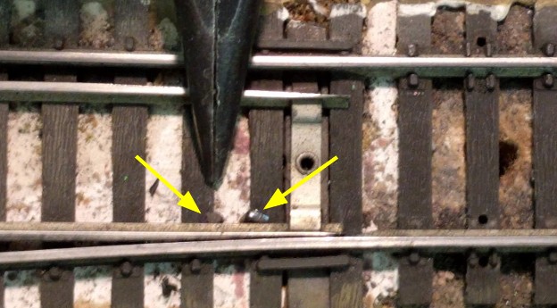
To avoid having it floating and thus likely shorting or derailing passing trains, the point was spiked in 2 places:
The second spike blends with the tie color and is hard to see visually:
Disconnect the Turnout from the Switch-8
The last thing I did is disconnect the Tortoises control wires from the Switch-8 outputs #2 (yellow wire on #2-A and green wire on #2-B) at the Mountain Panel. The two control wires are clearly labelled and just need to be screwed back into the outputs.
This will prevent anyone from mistakenly throwing the cross-over since only one side of the cross-over would throw.
Fix time: 2 hours.
2- Follow-up Fix
The follow-up is to remove the temporary fix and fix the turnout properly.
These are the tasks to be done:
- Remove the spikes from the point, as shown above.
- Clean the throw bar so that it can freely align in normal position.
- If the point can be made to close without force, then the same Tortoise throwbar wire could be used.
- If the point still requires some force to close, then a new throwbar wire should be manufactured using strong wire. There is some left-over in the electrical supply cabinet that seems suitable.
- The Tortoise throwbar wire needs to be put back in place.
- At the Mountain Panel, reconnect the control wires: yellow wire on #2-A (3rd position) and green wire on #2-B (4th position).


