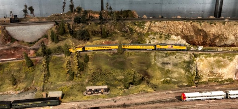
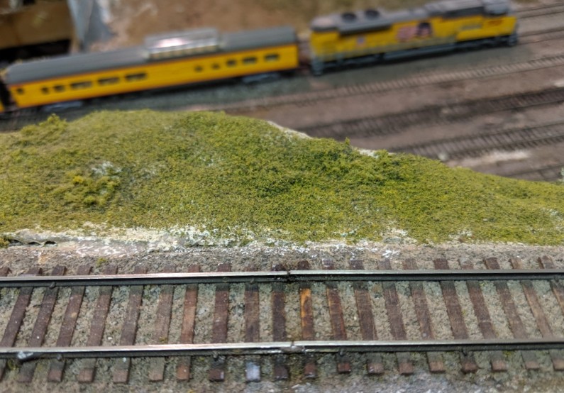
The Randall Museum in San Francisco hosts a large HO-scale model model railroad. Created by the Golden Gate Model Railroad Club starting in 1961, the layout was donated to the Museum in 2015. Since then I have started automatizing trains running on the layout. I am also the model railroad maintainer. This blog describes various updates on the Randall project and I maintain a separate blog for all my electronics not directly related to Randall.
2019-08-26 - Randall Repairs: Block B350
Category RandallAffected |
Block B350 up the mountain. |
Description |
Joiner solder gone bad. |
Summary Fix |
Resolder the joiner. |
Description of Issue
We have had elusive electrical issues with block B350 for a little while. Trains would stop when going up or down the mountain. This is likely due to a broken solder in the track power feeds -- as the track warms up or as the trains put pressure on it, it can be enough to make or break the contact and lose power. Or it could be an issue with the track power on the panel with the track toggles, as we had experienced issues with that last year too.
Although it’s easy to get a rough idea of where the trains lose power, it’s a lot harder to get near the track for a close inspection. A lot of these power feed wires are also hidden in the track scenery or ballast.
Description of Fix
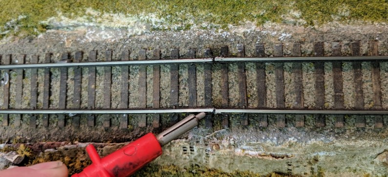
I finally repaired block B350 and this time it should work properly. This picture below shows where two flex track segments were soldered together yet I was able to move the rail with the multimeter probe. The solder joint had simply failed so I removed the old solder and put some new one in to make a good joint.
I was barking at the wrong tree before, and I only found the culprit by sheer luck.
I originally suspected the issue to be on the panel side. Maybe the toggle switch was wrong, so I bypassed it. Nope, it wasn’t that. Maybe the feed wire was wrong, so I disconnected it. Neither solved anything as the block was still powered -- but huh, did I just say it’s powered even when the feed wire was disconnected? So that means it’s powered from somewhere else and it was quickly obvious it was powered from block B340.
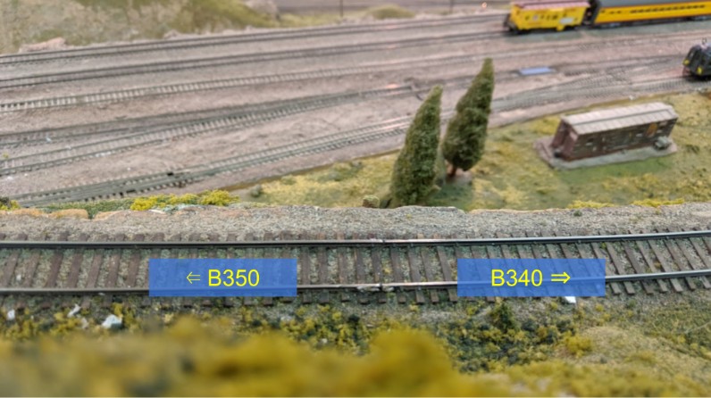
As I suspected, the junction between block B340 and B350 had been soldered to bridge over the block gap, with bond wires no less. Not a huge surprise as I’ve seen the same thing done somewhere else on the layout. It’s the typical solution of people who want a quick fix, and don’t understand why bother with blocks to begin with. Ironically even last week I’ve been “recommended” to do exactly that here, and such people don’t understand why I’m reluctant to embrace their “obvious” solution.
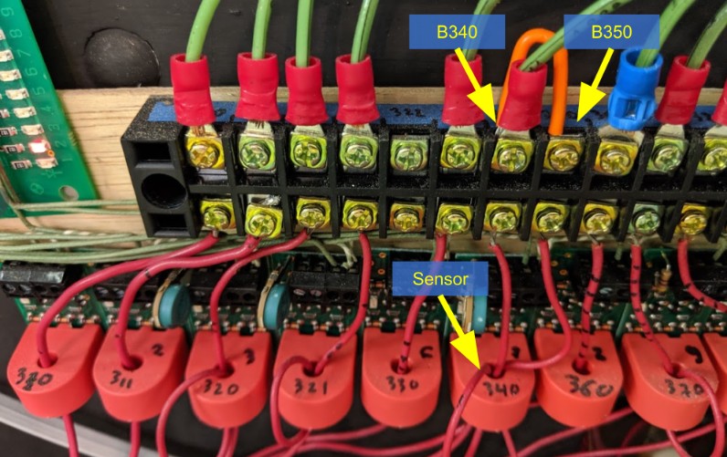
Anyhow I carefully cleaned the gap between both blocks and unsoldered the bond wires. Now both blocks are “mostly” separate, except I bridged them at the panel so that one block detector can detect both:
Eventually I plan to rebuild that sensor array and split B340 and B350 but for now that will do.
Now, all that did not solve the issue, and once again we had a problem with a train losing power there. And I finally figured it out. Block B350 is made of multiple flex track segments. The whole block has maybe two feed wires, but they don’t necessarily cover every single track segment. There’s a 1-foot segment between B350 and B340. It’s technically part of the B350 block and the rails are simply soldered to the next flex track segment. Except that is the place where I was able to trivially push the rail to make or break the connection with the meter probe, and that small segment has not feed wire. So depending on heat or another other random condition, this 1-foot segment was powered or not. Visually the solder joint looked just fine, yet the red side of the rail was not properly soldered on one side. I only found it by sheer while probing with the ohmmeter and noticed the rail could move a tiny bit when pushed by the probe.
I carefully removed the old solder, put a new one, and now that’s working again.
One can see the track feeder on the left side of the picture, powering a 3-feet flex track segment. The segment on the right side is only about 1-foot long, and is powered only via the solder joint in the middle.
Another solution would have been to properly add track feeders. I didn’t have any drilling tool at hand to drill through the plywood support. Maybe another time.
That’s one thing all tutorials will teach one these days -- solder every single track segment with feeders connected to a bus under the layout. Even if it feels overkill, just do it. Don’t rely on solder joints, or rail joiners, to make good connections. Long soldered sections have yet another problem, which is track expansion due to heat. There has to be a way for the track to expand/shrink with heat, and soldered joints don’t allow that -- instead they probably fatigue at each heat cycle and eventually break (which is what I’m guessing happened here). “I will fix it later” is one of these things that never happen -- and here’s a good example because adding a track feeder now is a lot more work than if it had been done when they built the layout. Access is harder, scenery is in the way, I don’t have the tools at hand nor the same skills, etc.
Fix time: hours.
