The Randall Museum in San Francisco hosts a large HO-scale model model railroad. Created by the Golden Gate Model Railroad Club starting in 1961, the layout was donated to the Museum in 2015. Since then I have started automatizing trains running on the layout. I am also the model railroad maintainer. This blog describes various updates on the Randall project and I maintain a separate blog for all my electronics not directly related to Randall.
2022-01-08 - Documentation Update and a Trip Down Memory Lane
Category RandallI’ve spent some time updating the Randall Documentation git repository. What’s changed:
- There’s a new hardware folder.
- Currently it only contains the PFM Fulgurex documentation.
- I plan to add more to collect the user manual of all the hardware we currently use on the train layout, from the command station, to the various electronic boards such as auto reversers or electronic circuit breakers.
- There’s a new ggmrc_history folder.
- This contains paper documentation I found on the layout’s archives. I scanned them all a few years ago. Scan quality was so-so; image contrast is really poor on many of these. I tried my best to find what they describe and rename them accordingly.
I was particularly interested in the historical documents I could find. They cover a wide time range, from 1965 up to 2010.
Layout wiring standard “adopted June ‘65”.
However these documents are a mixed bag. Some are early design schematics for the mainline or the yards, which may or may not be relevant today. There are some early construction standards for the layout. Others describe equipment which is not there anymore. There are a few yard or panel descriptions that I could not quite relate exactly to the layout, so these are labeled as ‘unknown’.
The older papers were hard to scan. Some are hard to read -- visually fainted pencil markings, or just plain cryptic. Contrast is really poor on most of the scanned material. That’s the best I could get out of them for now. All the electrical schemas labeled as being from the 60s/70s are more or less obsolete and irrelevant, except they give great clues in the initial design intention and the origin of the track design (e.g. some have their origin city names). Some of the latter documentation such as Fairfield or the Branchline from the 90s are spot on and quite useful to have.
The latter 2000-2010 documents are from Mr. Perry and are the ones I used as the basis to rebuild the Stockton, DFS, and Branchline schematics located here (after I spent quite some time crawling under the layout and validating they are neatly accurate and quite helpful).
DC-vs-DCC power selection wiring for the Branchline.
An example of “almost”, this next hand-drawn schematic matches the current Stockton Engine Facility to 75% of the track:
An early schematic, likely what is now the Stockton Engine Facility with its roundhouse.
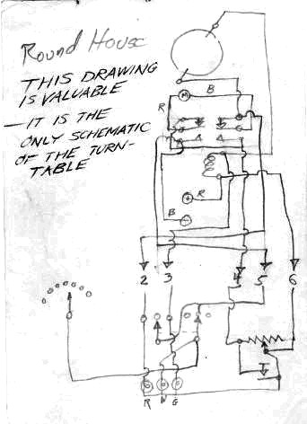
And this one is particularly amusing since it is “valuable”:
The “only schematic of the turn-table”.
Since I believe in the need for strong documentation for the train layout, I was quite glad to be able to capture these, even if it’s just for historical value. There are some quite neat hand-written schemas in there and I invite you to check them out in the ggmrc_history folder on the git repository.


