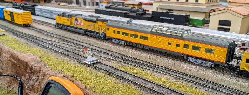
The Randall Museum in San Francisco hosts a large HO-scale model railroad. Created by the Golden Gate Model Railroad Club starting in 1961, the layout was donated to the Museum in 2015. Since then I have started automatizing trains running on the layout. I am also the model railroad maintainer. This blog describes various updates on the Randall Museum Model Railroad and I maintain a separate tech blog for all my electronics & software not directly related to Randall.
2023-01-07 - Randall Repairs: B310-B02 Dead Spot (Stockton Station)
Category RandallAffected |
B310-B02 between T01 and T02 in front of Stockton Station. |
Description |
Intermittent dead spot on mainline. |
Summary Fix |
Fix bad track joiner. |
Description of Issue
We've been having an intermittent dead spot on the mainline on block B310/B02, right between T01 and T02 in front of Stockton Station.
Location on the layout track map.
The dead spot is on the “bottom” section of the T01/T02 crossover. Depending on how the turnouts are thrown, this may be contiguous with either B310 to the left, or B02 to the right. In the default normal position of the turnouts, the segment appears to be powered by B310.
It took me about forever to find the spot because each time it was reported, by the time I’d get to the museum the thing would be working again. And due to this, it had all the hallmarks of a broken solder -- a minor crack in a solder that makes or breaks continuity contact based on rail/wood expansion due to temperature or humidity. I carefully examined the track inch by inch in that area and could not notice anything.
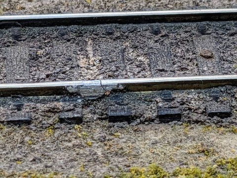
Finally today it happened when I was there and I was able to spot the issue:
What, you can’t spot it? OK let’s try to zoom in:
Now you can surely spot the broken solder on the lower rail.
To be clear, these things are to be expected on this 50-year old layout. Metal rails expand with temperature. The wood subframe shrinks and expands with temperature and humidity. Solders are not made to be flexible. That’s why these dead spots are intermittent -- with either vibration from usage, or temperature from the room, the metal can shrink or expand just a tiny bit and that can make or break the contact.
But wait, there’s a new angle to that below.
Description of Fix
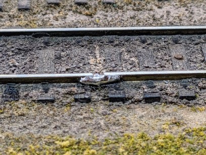
The fix here is simple… apply fresh solder. That spot is nice because at least it’s super easily accessible, so in no time I had this:
OK fine my soldering skills are quite frankly… unsophisticated. So it’s a bit of a blob, but it will get the job done. I used sand paper on the hot solder to ensure there’s none at the top or on the inside of the rail that would cause a derailment.
But then looking at this picture more closely I realize this is not your typical track solder joint -- what I see here is that there’s a “huge” 3 millimeter gap between both rails, which has been filled with solder instead of using a proper track rail joiner.
Fun fact and to understand why that is “huge”: a 3 mm gap at the 1:87 HO scale corresponds to a 2-foot gap in real scale. Imagine a 2-foot hole in a rail, filled with solder or whatever… That’s what we have here.
I’ll revisit this once I figure out a better way to address this.
Update 2023-01-11: I went back this morning to redo that solder joint. I simply did not like my previous clumsy fix. I also realized that I took the naïve approach of “filling” the gap, which means my fix will eventually have the same issue as the original one: it’s not flexible, and with temperature/humidity changes eventually the rail expansion will make it crack again.
First thing I did was heat the current solder and vacuum it, to get a clean gap:
I took a little piece of 24 AWG wire, tinning the wire, and held it in place, then soldered the wire on both end to the left and right rails, but not in the middle:
Here’s the end result… I pondered about filling the gap with solder, and decided against it. A quick test with a freight car showed me it rolled freely and smoothly over the gap, with no hesitation. I hope that, by leaving the gap empty, it will give room to the rails to expand with temperature and humidity, preventing the solder from cracking.
To prevent the new solder from being too shiny, I “painted” it using a black marker.
Here's a final quick test:
Fix time: 2 hours + many previous days looking for that spot.


