Model Train-related Notes Blog -- these are personal notes and musings on the subject of model train control, automation, electronics, or whatever I find interesting. I also have more posts in a blog dedicated to the maintenance of the Randall Museum Model Railroad.
2018-09-15 - NCE AIU01 and Motion Sensor
Category NCE
As previously discussed, on the Randall layout, visitors press a button to trigger the trains’ automated sequence. Soon enough, we added a sign asking people to be nice with that button. The sign has nothing to do with the actual electronics behind nor the automation, not even the button itself. Both the button and the software are sturdy enough to survive any abuse.
And abuse there is. The abuse is simply… social. Kids hammer that button like there’s no tomorrow. Does it make trains run faster or more frequently? Nope. One would hope it would be a good exercise in parenting in teaching kids to be reasonable and treat common property adequately, but alas, no.
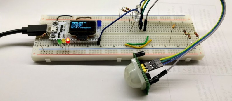
Eventually Jim and I had enough of it and I decided we could simply use a motion sensor as a trigger instead of a hardware button. Back in March, I built this prototype:
The original design for the motion sensor was to use an ESP32 with an HC-SR501. The ESP32 would be used to send a sensor activation command to JMRI.
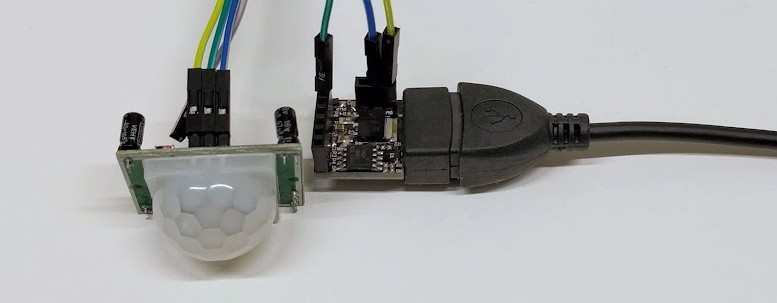
Since I was working on RTAC, it occurred to me I could use it to drive a Digispark Tiny via a wired USB connection and the same sensor. Then RTAC could just manipulate a Conductor variable directly over the KV server connection. This has the advantage that it removes the requirement for wifi. One less dependency. Or does it?
Well not quite. Instead it creates a dependency on a tablet driving the arduino. Which means if the tablet fails, there is no automation at all since there’s no motion sensor. That totally contradicts one of my earlier design goals: the tablets are accessories and never mandatory for the automation to operate.
When I implemented the motion sensor polling on RTAC, I decided to not use it to drive the automation right away and instead I’d monitor it for a while. I added GA analytics so I could track how many times it got activated and for how long. That worked well for a few days then nothing for the next two days. What happened? There are plenty of unknown variables here: the arduino could have failed, or the PIR sensor, or the tablet, or the wifi connection (remote check indicates the tablet doesn’t show up on the wifi network). That’s a lot of failure modes for something that is supposedly critical for the automation.
Thus I went back to the drawing board, and decided to use the ESP32 as I did in the prototype or some other mechanism. Also in this case, I would not necessarily have to replace the tablet-driven sensor. I could have multiple sensors and use them all to perform activations. It would give even better coverage and offer redundancy, at the cost of a somewhat more complex implementation. Would it be worth it?
When in doubt, simplify. Remove variables instead of adding them.
What is the shortest path / easiest implementation using an ESP32? The original plan was for the ESP32 to monitor the HC-SR501 sensor and then issue an HTTP POST to the JMRI JSON server, to turn on a virtual sensor entry or an existing unused NCE AIU01 one.
It then occurred to me I had another option: I already had a microcontroller board always powered which I can poll using the automation control software -- the same NCE AIU01 board that used to monitor the activation button.
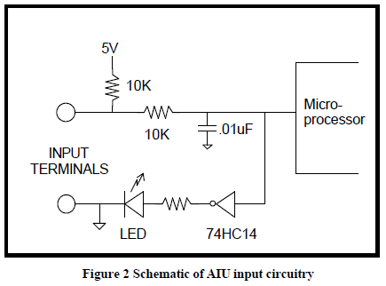
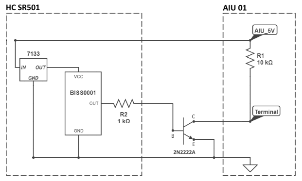
Normally the inputs on these NCE AIU boards are supposed to be contacts, whereas here I have an active circuit. When I experimented with the NCE AIU01 and IR sensors, I had no problem driving an IR LED from that NCE AIU01 board directly. In a similar fashion, I could drive the HC-SR501 directly from an NCE AIU01:
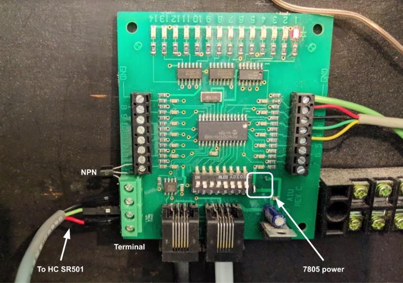
- The AIU01 has a 7805 voltage regulator and I can get 5V by soldering a wire in one of the through-holes on the PCB.
- The 3V output of the SR501 can be used to drive the AIU terminal, but not directly.
Looking at the HC-SR501 datasheet (link via Aliexpress):
- The SR501 uses a 7133 voltage regulator. We can feed it with the 5V from the AIU’s 7805.
- The BISS001 drives the OUT pin directly via a 1kΩ resistor.
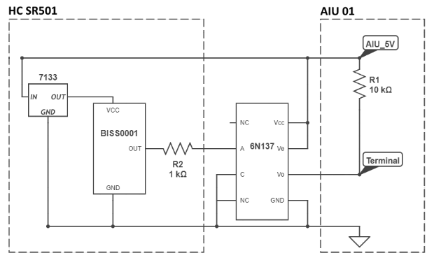
The BISS0001 datasheet (link from Ladyada) shows an example of driving a relay via an NPN transistor. A single 2N2222A, or maybe two of them in a darlington pair (example here) should do the trick. Another option is to use a 6N137 single-channel optocoupler (C=Gnd, A=Out of SR501, VCC=5V power of AIU/SR501, VE=high or NC, VO=Invert of A). It would be a very good match with the AIU which has pull-ups on all terminal inputs. I happen to have a bunch of these optocouplers as they are quite convenient to build simple Arduino DCC monitors.
In theory, that works since the output Vo of the 6N137 needs to be driven high by a pull-up, which the terminal of the AIU conveniently provides. There needs to be some load, which in my bench test was a 4kΩ resistor and a LED.
In practice however that doesn’t work with the SR501 driving the 6N137 input. The expected min current IFH is 5 mA, which on a 3.3V would be 660Ω. But the SR501 supposedly already has a 1kΩ on the output, and it does measure as such on the sensors I have; we can hardly expect more than 3.3 mA on the output, well below the minimum 5 mA expected by the 6N137. Experimentation quickly confirmed that it did not work.
So back to the 2N2222A design, using the most simple one:
The positive aspect of doing it this way is that it’s one less arduino to program and maintain. No reliance on wifi either. It relies on the AIU for power and signaling, which is a given in my automation scheme anyway.
In practice, I ended up with this:
I added a 4-position terminal to wire the sensor. From bottom to top: +5V (red), SR501 output (green), ground (black). The 4th terminal position is wired to the sensor output and connects to the base of the NPN transistor. +5V/ground are easily picked up on the through-hole connections just above the condensator next to the 7805.

