Model Train-related Notes Blog -- these are personal notes and musings on the subject of model train control, automation, electronics, or whatever I find interesting. I also have more posts in a blog dedicated to the maintenance of the Randall Museum Model Railroad.
2023-09-18 - Converting a Bachmann Spectrum Shay to DCC
Category DCC
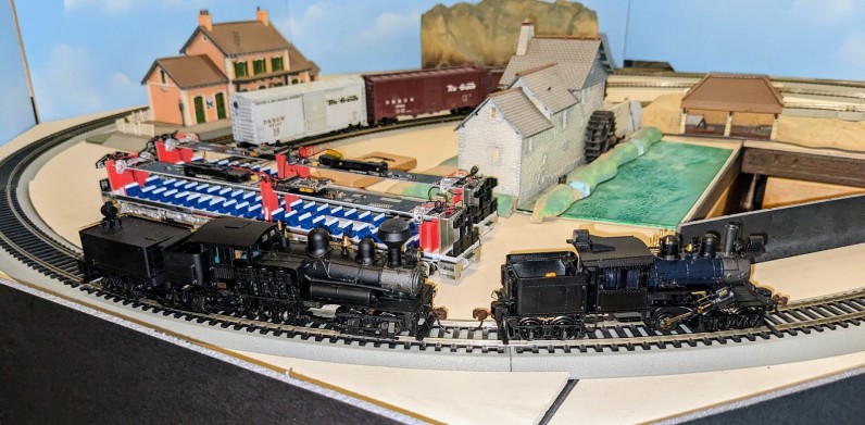
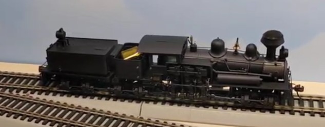
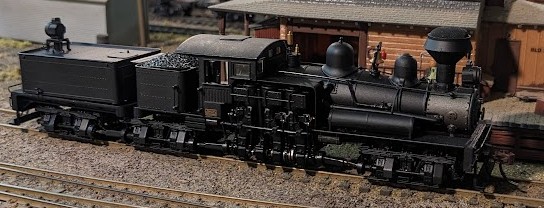
The Shay running at Randall after DCC conversion.
I recently got a Bachmann Spectrum Shay -- the “80-ton 3 truck Shay” #81901. The one I got is an unlettered black version, used, and in good condition. All gears work. It has an 8-pin NMRA / NEM652 connector, and it screams to be converted to DCC so we’ll discuss this effort here.
The Bachmann Shay before DCC conversion, as unboxed.
Initial Observations
Here are the initial observations:
- Runs on DC by default. There's a circuit board in the rear tender with an 8-pin NEN652 connector for a "direct" DCC decoder installation.
- Motor seems OK, running smoothly, all pistons and gearing functional for traction.
- Front light doesn’t seem to turn on.
- Doesn’t seem very obvious to replace. Cannot tell by the pictures here.
- The front smoke door just pulls easily, revealing a light bulb + plastic light guide (but allegedly no easy way to pull the bulb from there).
- Rear light does turn on.
- The rear light is a bulb. Seems like it’s on the circuit board (see image below), with a plastic light guide.
- There’s a firefox red light inside, does turn on.
- That’s one more bulb. Supposedly accessible by removing trucks + pistons.
- Box contains the documentation, “coal” weight, accessories (optional toolbox, water hose, some other little details).
- The coal tender is 15 x 29 mm.
- The coal weight could be replaced by a 3d-printed cover.
- Tender from the outside is 48x32x18mm but that’s not usable space.
- From a discussion online, 3-truck shay tender shell removal:
- “dcc board will go inside the articulated tender, the sugar cube speaker will go in the main tender.”
- “Remove the tender truck and the rear truck on the main frame. This will expose the 2 mini plug connections, a slotted head screw that holds the draw bar from the loco, and finally a Phillips head screw beside the draw bar screw. Remove the phillips head screw and the tender cover pivots off from the front to the rear, the rear is hinged. Be careful in regards to the ladder and sanders on the back of the tender. There is an 8 pin plug for connecting the decoder to. While you're in there, remove the yellow capacitor to improve running abilities.”
- Tender’s screw can be accessed by simply rotating the middle truck (remove the crew, carefully rotate it around the driving gears). The tender screw is “held” in place by the draw bar (it overlaps slightly).
Need to pull the tender forward slightly before lifting it, as there are metal pivots at the back. The ladder can be detached on the tender side. - Tender features a 8-pin NEM652.
- Tender space is 40.9 x 26 x 13 mm, but the usable space is really 35 x 26 mm (due to rear LED conduit) and height is 13-7 = 6 mm above the 8-pin plug.
- Front part disassembly -- don’t go there! Geared Steam : Bachmann Spectrum Shay Disassembly
- The Bachmann Spectrum Shay is said to be a really good model.
Review: Bachmann Spectrum HO 3-Truck Shay review - Model Railroader Magazine
(an overall good review, worth reading). - Known issue: the bevel gears can crack, or even come cracked out of the box (!).
- Replacement gears:
Bevel Gear, HO Bachmann 3-truck Shay (81907) 80-ton, 3 Truck upgrade b – NorthWest Short Line. - Upfront I applied a little bit of grease to all the visible drive gear. The only part I have not done yet is lubricate the motor bearing and the worm gear inside, due to the difficulty of access.
DCC Decoder Choice
All gears seem to work on that one, so I’m going to ignore the gear issue (we’ll burn that bridge once we get to it), and focus on adding a decoder in there. Obviously what I want is a DCC decoder with sound, and I have options.
- TCS M2 or M4:
- MC2 - TrainControlSystems
- MC4 - TrainControlSystems
- Their spec size is 18.02mm x 10.63mm x 4.85mm
- No sound. Wires + optional 8-pin plug (with long wires).
- TCS DP2X-UK uses an 8-pin NMRA compatible TCS decoder.
- No sound either.
- The common "blue wrapped" Digitrax Decoder DH126
- Digitrax - DH126D 1.5 Amp Economy HO Scale Wired Mobile Decoder
- Size 17.08mm x 27.28mm x 6.6mm
- Tsunami decoder TSU-1100
- Soundtraxx Tsunami2 Digital Sound Decoder TSU-1100
- Size of 27 x 10.5 x 5mm
- Soundtraxx has a dedicated board replacement + decoder + speaker here:
SoundTraxx - DSD-B3TSLC for Bachmann HO 3-Truck Shay - 678-820060 - LokSound 5 “micro”.
- ESU - LokSound 5 micro / LokSound 5 micro DCC
- Size either 25mm or 21mm x 10mm x 5mm depending on the page that I read.
- Can come with a 11mm x 15mm sugar cube speaker
- Note that the version with the 8-pin wires seems longer -- the 8-pin connection is actually a ribbon, so it can’t be cut/shortened easily, and on the decoder side it has a little board that plugs in the Next18 socket.
Even the “wire version” is using a little Next18 socket with wires. - Caution: what they call an “8-pin” is NOT an “8-pin NMRA” on the pictures even though it says so in the text!
- Shay sound file for LokSound 5 here: LokSound 5 North American and Australian Sound files - ESU
That sound is ridiculously gorgeous. - Bachmann 81945:
- Decoder 8 pin plug (HO Universal) [81945-44915] - Bachmann Store
- Supposedly the one to fit in there.
- I actually found later that I have one of these, that I pulled out of an old loco where I replaced the decoder. No idea if it works. No sound.
One option is to use the existing 8-pin NEM652 plug. References:
- https://dccwiki.com/8_Pin_DCC_Plug → how to test it, how to wire it.
- https://www.morop.org/index.php/en/nem-the-norms.html → search 652.
In the end, I ordered a LokSound 5 “micro” “with wires” instead of the dubious 8-pin version:
- ESU - LokSound 5 micro / LokSound 5 micro DCC
- I already have an ESU 11x15 sugar cube speaker in my stock pile at home.
Speaker Placement
While I await for it to arrive, I cut templates out of cardboard based on the dimensions of the speaker and the decoder, to see how I’m going to fit it all in there. Possible placement choices:
Where should the speaker go?
- There are no holes in the rear tender, so the speaker would be muffled there.
- Placing the speaker in the coal tender would require drilling some holes through the metal casing. I don’t see any obvious way to route wires from the bottom.
- Decision:
- I will first try with the speaker in the rear tender, and evaluate how muffled the sound is.
- Then I can compare with the speaker in the coal tender, simply by routing the wires outside of the tender at first.
- If I end up liking the coal tender placement, I’ll drill a small hole in the partition between both tenders.
- In that case, I can 3d print a “coal load” cover since I would not be using the original all-metal die cast one.
I’m not going to deal with the lights yet. The front bulb seems dead, and seems like a PITA to replace. The rear one is easily accessible on the rear tender circuit board. The firebox one needs a serious disassembly too to access it. It’s said that DCC wears out light bulbs faster, mostly because the lights are always on at full power (compared to DC). Not sure how much true that is. The only thing I know is that I’m not going to change them now, and if/when I do later, it will be to go for LEDs.
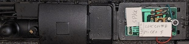
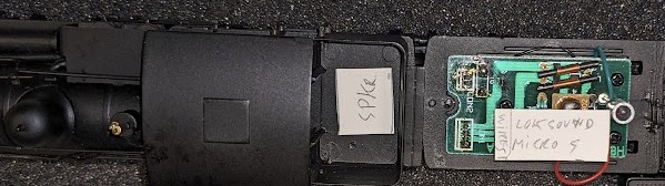
Tender Circuit Board
Now let’s address the issue of the rear board and the 8-pin connector.
Pulling the board revealed 2 black wires directly connecting to the rear truck, one being smashed by the tender cover. Can be seen broken on the top of the right picture above. Will need to be resoldered/fixed.
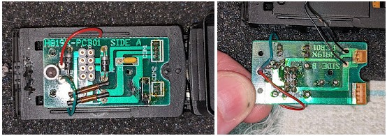
Schematics of the current board:
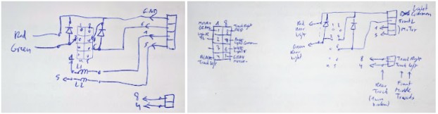
https://cs.trains.com/mrr/f/744/t/209123.aspx suggests removing the cap, but leaving the inductances as having “no effect without the cap” (hmmm, that’s not really how an LC network works… my guess is more that it does not have a strongly noticeable effect).
The argument can indeed be made to pull most of the components off the board and solder directly to it: none of these components are really useful.
- The diodes are only useful in DC: because the “DC plug” bridges track/motor/light pins, there is no connection to 7 (the light common). Instead it’s the diode providing it on the light that is off. E.g. one of the diodes is always passing and the other one blocking. Thus they must be removed. It’s even explained in the NEM-652 doc here (page 2).
- The cap is in between the motor leads (1-5), and that will negatively affect BEMF.
- The inductors are in series with the motor leads (1-5), and it probably has a small negative effect on BEMF, even if likely negligible.
In the end I removed all these, and since I had my fancy RadioShack desoldering iron all hot and primed, I also removed the 8-pin plug entirely:
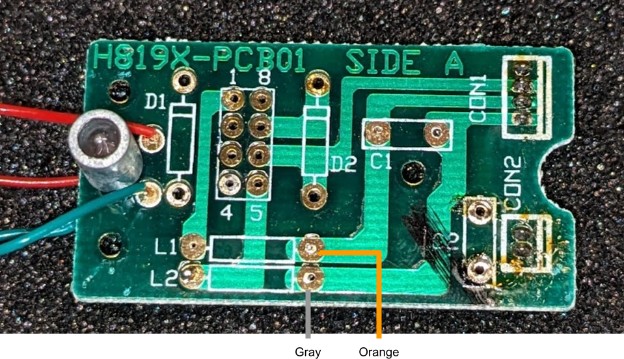
We’ll wire it as such:
- Orange wire → Directly to old L1 (on connector side). We don’t use 1.
- Gray wire → Directly to old L2 (on connector side). We don’t use 5.
- Red wire → to 8.
- Blue wire → to 7.
- White wire → to 6.
- Black wire → to 4.
- Yellow wire → to 2.
- Rear truck reconnects to “C2” (next to Con2) with the ex-broken wire (truck left) at the bottom.
- The two brown wires go to the speaker.
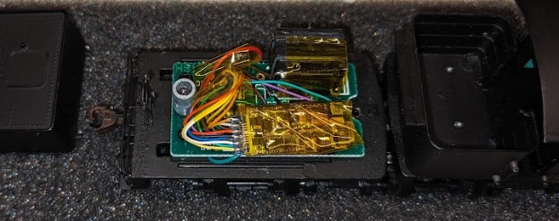
Here's a first version with the LokSound micro soldered, including the speaker. I left all the wires that came with the LokSound as-is because I had no idea how short I needed them. Also the speaker might go in the middle tender, and the original length of wiring makes that possible. Doesn’t look tidy yet that's enough to validate the setup so far.

I (double) checked all connections then loaded the Shay sound project using the LokProgrammer. That took a good half an hour to load.
Deciding on the Speaker Placement
I did 2 runs, one with the speaker in the rear tender with the cover on, and one with the speaker in the middle tender:
I was originally afraid the full metal enclosure of the rear tender would mute the speaker sound. However when I tried, that was not the case. Almost the reverse actually, I preferred the sound with the speaker in the rear tender. Why?
Measuring the sound with a volume level app on my phone revealed an interesting difference:
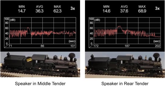
The sound has a noticeable high frequency component. On a Tsunami 2, I'd adjust that with the equalizer, but here the LokSound, ironically how fancy it is, lacks that option. When the speaker is in the enclosed rear tender, the high frequency hiss is much less pronounced and the bass actually sounds louder. This is confirmed by the sound level app. The average and the max are higher with the speaker in the rear enclosed tender. The gap with a dome in the sound recording is the horn, and we can clearly see it higher on the picture at the right.
Thus I’ll keep the speaker in the rear tender. It sounds better, and I don’t have the hassle of passing the wires through between both metal tenders. Now the trouble is making it all fit, and with the bundle of long wires I originally had, there was no way to close the tender properly.
Eventually I ended up with this setup:
To be able to fit everything, I had to desolder the decoder, cut the wires, then resolder them. Tedious but easy, and I was planning to do that anyway. The real fight was trying to put the tender cover back and screw it in place, which is quite an ordeal (which I'll describe below).
After multiple tries and retries, I got the result seen below. Although it’s subtle, it is visible that the front of the tender does not fully close. The problem is that the speaker is just a tad too big, by about one millimeter.
For the speaker, I used the ESU 50321 11mm x 15mm Sugar Cube Speaker 8 Ohm. This one has a “configurable” baffle -- basically a few plastic pieces that one assembles and glues together to form the desired shape and height. I used the max height possible, after I measured twice and estimated the space to be sufficient. Turns out it’s not, and in retrospect ideally I’d have used one less height segment.
I don’t have another speaker to assemble at hand. One option is get another one, or 3d print my own speaker baffle that is adjusted to the space I actually have here -- I’ve done that with great success for other sound installs before.
Whether I eventually do that depends on whether I’m bothered by the tiny little space visible at the front of the tender. I posit that open space, how tiny it be, is likely beneficial to allow the sound to get out of the tender. So unless I’m visually bothered by it, I may just keep it that way for now.
Opening and Closing the Rear Tender
This part requires some explanation. It took me a while to figure out how to do it, even with the explanations that I had seen online.The rear tender is a metal cover. It’s pretty sturdy die cast metal, almost 2 mm thick. The rear part of the tender is held by two little tabs, and the front part is locked by a screw. To remove the cover, one “merely” needs to remove the screw, and then tilt the tender towards the rear. Reverse the operation to install it back.
Accessing that lone screw is the challenge: it’s accessed via the bottom, but it’s covered by the rear draw bar, the circuit board connectors, and the middle truck. Here’s the order of operations:
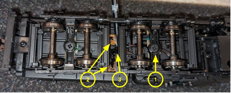
1- Remove the middle truck screw, and pivot the truck -- no need to remove it entirely, I just hold it on its side:
2- Disconnect the 2 orange connectors from the circuit board.
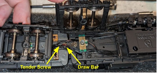
3- The tender screw is now visible, slightly covered by the drawbar.
Since the drawbar overlaps the tender screw, it’s actually possible to just leave the drawbar in place -- that basically holds the tender screw in place and prevents it from falling off.
To remove the tender cover, unscrew that tender screw, then lift the front of the tender. Remember to snap off the ladder in the back first, the top of the ladder simply snugly fits in little holes in the tender.
To put the tender cover back, fit the back tender tabs first, tilt it down towards the front, then flip the engine over and do the same operation as above to access the tender screw. It’s very much recessed, making it hard to hold in place with pliers while screwing it, so for that part I had to unscrew the rear part of the drawbar to get better access.
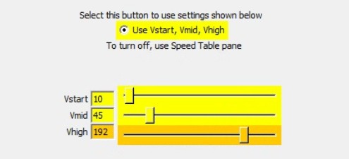
Adjusting the DCC Speed
I need to reconfigure the CVs for Vstart/Vmid/Vhigh. They defaulted in the LokSound project to 2 / 45 / 128.
CV 2 (Vstart) at 2 was too slow, the motor was barely moving. I changed that to 10, which allows the engine to crawl at speed 1.
CV 5 (Vhigh) at 128 is too low. It means the top speed of the engine is only half of the motor output, and it’s quite a crawl. I would not go to the max, yet a value such as 192 seems more reasonable.
So how fast is that engine really going? I’ve tried 3 values for Vhigh, ran the engine on a 3-foot section of track, timed it going forward, then backward, and measured an equivalent to 1:1 speed:
Vhigh (CV 5) |
Distance (m) |
Forward (s) |
Reverse (s) |
HO speed (m/s) |
1:1 km/h |
1:1 MPH |
128 |
0.9144 |
34 |
66 |
0.01385 |
4.3 |
7.0 |
192 |
0.9144 |
24 |
44 |
0.02078 |
6.5 |
10.5 |
255 |
0.9144 |
18 |
35 |
0.02613 |
8.2 |
13.2 |
I’m going for the 3/4th value of Vhigh CV 5 = 192, with a Vmid of 100. I never run my engines full speed as there’s little benefit in pushing these tiny motors to their max voltage. That will give it a “real” top speed of about 10 MPH, which is significantly less than the accepted 15 MPH top speed for a Shay yet still appropriate.
End Result and Future Changes
And voila, I currently have a functional DCC-equipped Shay locomotive. There are a few more things to take care of, but these will be projects for another time:
- Reconfigure the CVs for Vstart/Vmid/Vhigh (done).
- Consider 3D-printing a different speaker baffle, adjusted to the space available in the tender.
- Consider upgrading the lights to LED and fixing the front light.
- Consider lettering and numbering the engine.
To be continued…