Model Train-related Notes Blog -- these are personal notes and musings on the subject of model train control, automation, electronics, or whatever I find interesting. I also have more posts in a blog dedicated to the maintenance of the Randall Museum Model Railroad.
2024-08-04 - Ringing a POTS Phone
Category Electronics
Orion is working on a project: creating an internal intercom system for the Randall Museum Model Railroad.
One of his requirements is to make the phone rings using their internal ringer, without modifying the phones, or without using the easy solution of simulating the ringer using an arduino+speaker setup.
That means we need to simulate the POTS signaling for the ringer on his closed phone line: such phones ring when they receive a signal 90 V AC at 20-40 Hz:
- https://www.jkaudio.com/article_10.htm
- https://pbxbook.com/other/trunks.html (fascinating details including railroad origins)
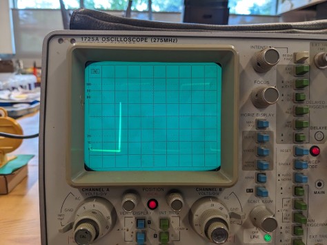
Orion and I looked at his BlueTooth phone adapter -- the ring does provide a 90~100 V signal at about 20 Hz. We checked that with a real old-school scope. One thing I did forget to measure was the current draw, doh. But since the adapter is powered via a regular USB brick, it can’t be more than 5 W (1A x 5V).
Thus the goal is to make some circuitry, the simplest possible, that will generate a 90~100 V DC square signal switched at 20 Hz. And, as an extra precaution, I want this circuitry to be isolated from the power grid.
Generating a 20 Hz signal
So first I need to make a 20 Hz signal. That’s easily done with either an NE555 or, for experimenting, an arduino or ESP32. I think the end circuit will be an NE555 so maybe start there.
Random NE555 datasheet: https://www.ti.com/product/NE555 [pdf]
- This has a supply voltage range of 4.5V-16V.
- Output current is 200 mA… This ain’t no power circuit 🙂
Section 8.3.2 gives us the A-Stable operator schematic and what we need for it.
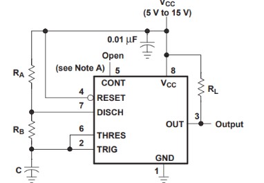
RL = 1 kΩ
In this case, we want a 50% signal at 20 Hz.
- 50% signal means tL = tH (time low = time high), and tL/tH = Rb / (Ra + Rb) ⇒ Ra = Rb.
- Frequency is f = 1.44 / (Ra + 2 Rb) . C
- Since Ra = Rb, the formula becomes:
- f = 1.44 / (3 Ra . C) = 0.48 / RC
- R = 0.48 / f.C
- C = 0.48 / f.R
Example values that would work:
Ra = Rb |
C |
Frequency |
22 kΩ |
1 µF |
21.8 Hz |
10 kΩ |
2.2 µF |
21.8 Hz |
4.7 kΩ |
3.3 µF |
30.9 Hz |
4.7 kΩ |
4.7 µF |
21.7 Hz |
For the input, we can use any 5 V USB power supply, or the 12 V DC power supply that already powers the internal phone network.
Now the output of the NE555 is a meager 200 mA, so we’re not going to drive anything serious with that.
One idea is to generate a 90~100 V DC signal somehow and then use the output of the NE555 to chop that DC signal using either a relay or a transistor.
Except we cannot use a mechanical relay (these could not stand a 20 Hz switching), and we cannot use a solid state relay (SSR) either -- these are basically TRIACs and they can only switch an AC load. They cannot switch a DC signal (*). Note that however 20 Hz is fine for an SSR.
(* unless using a so-called “DC-to-DC Solid State Relay” which typically use a MOSFET internally or some kind of GTO. These exist but are more expensive than the ubiquitous cheap SSRs.)
Thus the ideal way to do our switching is to use a transistor, or more precisely here a MOSFET. It has to be able to switch ~100 V DC. There are various kinds of MOSFETS -- N-channel vs P-channel, but most importantly the gate voltage to make it switch (Vgs): most IRF models have a 10V voltage (aka “standard level”) and IRL have “logic level” voltage of 5V -- except apparently some IRF models do have a Vgs way lower than 10V.
For this application, I could use something like an IRF640N which can switch 200 V @ 18 A with a Vgs of 4V. These are ubiquitous such as in these MOSFETs clone kits.
Generating a 90 V DC signal
Finally, we need to create that 90V DC signal.
First off, I wonder if we really need 90 V DC. My first experiment would be to generate a 20 Hz signal as above and switch the output of an DC-to-DC boost converter such as https://amzn.to/4cawnUB -- this can generate up to 45 V, which we could feed from the same source of power as the NE555.
Assuming that doesn’t work and we really need 90 V, we can use a voltage multiplier.
This page explains a lot of voltage multipliers so I won’t repeat it here:
https://www.allaboutcircuits.com/textbook/semiconductors/chpt-3/voltage-multipliers/
These need an AC source. Luckily we have plenty of AC power supplies around. The layout even has a 12 V AC bus (more like ~10.5 V actually) to power the old twin-coil switch machines. And we have some left-over “toy brick style” AC-to-DC train power supplies which typically have a fixed 16 V AC output for accessories. Note in this case, we would need about 6x amplification (16 x 6 = 96 V, which will probably be ~70 V after loses) and a 1 A supply would result in ⅙ A output (~160 mA).
The other way to make a “DC-to-DC” voltage multiplier without using an AC source is the use an NE555 as the switching source:
https://elonics.org/dc-voltage-doubler-circuit-using-555-timer/
If we can power the NE555 through a 12 V DC power supply, we’ll need a 8x stage multiplier to reach 96 V (actually a lot less than that, likely around 70 V to be realistic).