Model Train-related Notes Blog -- these are personal notes and musings on the subject of model train control, automation, electronics, or whatever I find interesting. I also have more posts in a blog dedicated to the maintenance of the Randall Museum Model Railroad.
2024-11-21 - DC-DC Boost Step-Up Converter XH-M411
Category Electronics
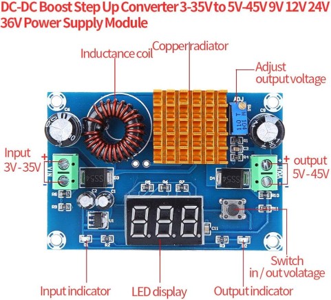
I got these for Randall and they are working very nicely: https://amzn.to/4evzCYk “DC-DC Boost Converter, XH-M411 DC to DC 3-35V to 5-45V (2 pack)”. The cost was $6.50 per converter.
There’s no usage manual (or I lost it?), so let’s copy stuff here:
What the button does is switch the display from displaying input to displaying output voltage. The blue LED turns on on the input/output side depending on what is displayed.
Output voltage is adjusted using the tiny blue potentiometer next to the radiator.
More specs and instructions here, so let’s copy what’s useful later:
- Input : 3V-35, 5A peak.
- Output is 5V-45V, 5A peak, adjusted using the blue potentiometer: clockwise to boost.
- If output voltage cannot be adjusted and matches input, turn potentiometer counterclockwise (step-down) till it starts to change.
- This is only a boost module. Output voltage must be greater than input voltage
- For example at Randall I was considering using a 24V DC input to output 16V DC… that won’t work.
- Integrated voltmeter is accurate to +/-0.1V in the 5-30V range.
- It will not display if input is lower than 4.5V.
Side Note / Tip on that peak 5A: power through a DC-DC converter has to be constant -- output power cannot be more than input power. Power is measured as “P = U . I”. That means if a DC-DC converter is used to, for example, double the voltage, the output current will be half of the input current. What the spec above means is that overall that converter can’t handle more than 5A both on the input side and the output side. Since this converter is a voltage booster (i.e. output voltage is higher than input voltage), that means the effective output current will always be less than the input max 5 amps. In other words, don’t even think you can get 5A on the output and a voltage boost at the same time. That’s just not realistic.
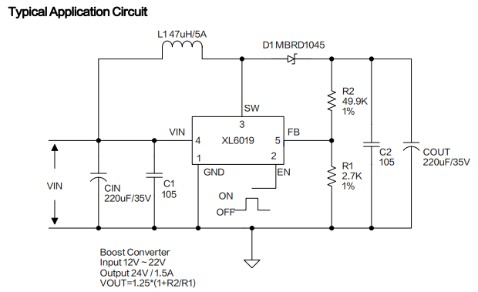
According to this instructable, the IC under the radiator is an XL-6019F (Datasheet PDF).
For one application, I have one of the Randall’s 12V AC bus nearby so I’m thinking of powering the device using that instead of the typical USB power brick. We have some diodes that look like the typical 1N4001 that seem perfect for this application, and I should add some random capacitor filter. OTOH I see that the board already has next to the input:
- A 220 µF 50V capacitor.
- An SS54 Schottky diode (Datasheet PDF).
That 220 µF capacitor unsurprisingly matches the XL-6019F typical application circuit:
So I’m going to venture that just a 1N4001 would be enough:
Disclaimer: I haven’t tried it yet. Of course to power this from an 12V AC bus, it wouldn’t hurt to use a full bridge rectifier and even more smoothing capacitors. But at that point, one could just use any low voltage AC-to-DC converter because that’s exactly what they do.


