The Randall Museum in San Francisco hosts a large HO-scale model railroad. Created by the Golden Gate Model Railroad Club starting in 1961, the layout was donated to the Museum in 2015. Since then I have started automatizing trains running on the layout. I am also the model railroad maintainer. This blog describes various updates on the Randall Museum Model Railroad and I maintain a separate tech blog for all my electronics & software not directly related to Randall.
2021-07-02 - Understanding the Building Lighting Panel
Category RandallI’ve been trying to update my documentation on the Building Lighting panel on the layout.
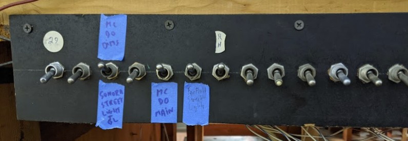
As a “recap of the previous episode”, under the Valley Panel 1 is located a row of toggles for “Scenic Lighting”:
Besides a few numbers (1 to 29), there’s not much indication on what these do.
Looking at my old emails, back in 2015-02-09 (before the GGMRC club donated the club to the museum in December 2015), I tried to understand this panel to light up the Fairfield town. Back then no lights were working and I “fixed” the power supply by replacing the fuse -- after finding they had the appropriate fuses behind the Stockton Yard panel.
From my notes, the fuse for the bulky 1997 power supply is a “5A 250V 313 Slo-Blow in a 31.75 mm (1 1/4") glass cartridge”. Here’s a mouser link for that kind of fuse.
So let’s try to decode all this. First, which toggles do produce any kind of lighting today? Allen and I could only find these below illuminating anything on the layout:
From left to right:
- 27 = Branchline, Sonora Street Light (by the branchline) and the illuminated car on the Branchline at Smith Flat.
- 25 = Mc Donald’s building.
- 24 = Fairfield street lighting (along the street with cars) + the Bekins yellow building.
- 23 = Labeled “R H”, powers a circuit in the Roundhouse (disconnected) + a shed nearby.
None of the other circuits seem to do anything. Either they are not used, or they go to places which are not connected, or dead lightbulbs. A bit more of this below; the bottom line a lot of crawling under the layout is involved to figure stuff out.
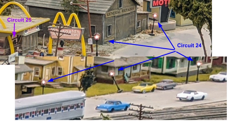
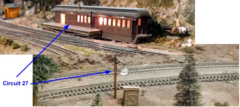
What we could both see on the layout:
Circuit 23, “RH” (hard to see but there’s a wire with some blue tape in the roundhouse):
Circuit 24, Fairfield has many illuminated street lights, and Circuit 25 for Mc Donald’s interior:
Circuit 27, on the Branchline:
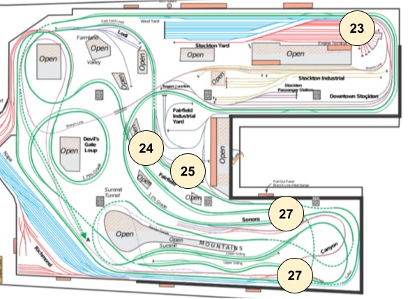
Representing these on a map of the layout:
As far as power level goes, the power supply:
- Delivers 15 V when all circuits are off.
- Delivers 10.3 V when the Branchline (27) is turned on.
- Delivers 9.3 V when the McDonalds (25) is turned on.
- Didn’t try with the Fairfield + RH on.
The branchline circuit seems to generate quite a significant power drop given the two paltry lights it powers.
It’s not a good sign to have such a voltage drop. I did not measure the amps delivered. I should do that. My guess is some of these use too much current and the power supply just can’t keep up. In which case I may have to change it if we’re going to power more circuits with it.
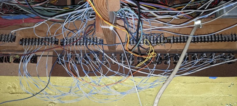
Now under the layout, we get to see an interesting story. First, on the other side of the row of toggles, we find this:
It’s a bit hard to see in that picture but there are a few interesting facts:
- Front toggles are numbered 1-to-29 from right-to-left (with only 3 number stickers visible, 9, 10, and 29).
- Terminal blocks on the back are fully numbered, yeah! Oh but wait, they are also numbered 1-to-29 also from right-to-left… See the problem here? Because they are on the other side of that panel, that means they are numbered in the wrong direction. Essentially front panel toggle #29 connect to terminal block #1, and front panel toggle #1 connects to terminal block #29. Oops. I’m fully familiar with that rookie mistake, having made it myself more than once…
- Even without zooming on that picture above, it’s clear a lot of these circuits are not used.
- Out of the 29 circuits, there are 10 wires leaving the panel towards Fairfield, and 3 wires leaving the panel towards the Roundhouse.
- All the wires have the same color… including the ground ones. Mostly. Yes, lovely.
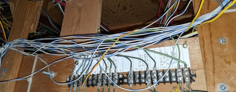
Next to that terminal block, I saw this and got a bit excited… finally some documentation?!
Well, nope. The white-with-blue wires are the building light circuits. They just pass through. The green wires are the ones going to the terminal with some labels about blocks. Not quite sure which bus that is, as green wires like this are typically used for turnouts in pair with white wires, and red wires to block power; yet the labels are more indicative of block power. Another mystery for another time.
Anyhow, looking at the details of the terminal blocks, there’s a large 20-position on the right that is unused. Then it’s followed by a 10-position block that seems to be mostly all for common wires judging by how the bottom terminals are all bridged together:
The only circuits that are wired are on the terminal blocks on the left side:
We need to keep in mind that the numbers are inverted with regards to the toggle panel. On the very right side, the big white-with-black wire is likely a ground. Then the one next to it goes to panel toggle #29. From this, it looks like we only have 12 outgoing circuits. That more or less matches the bundles of wires I’ve seen going out towards Fairfield (about 10) and towards the Roundhouse (about 3, including ground).
One of these wires from the 10-ish bundle going towards Fairfield seems to loop back under the Stockton Station. However it’s not clear where and if it is used. The Stockton Station has its own lighting circuit which is done using a completely redundant and independent old Bachman DC power pack, with nothing happening when I try to power it on.
One realization I had is that these were powering incandescent bulbs, likely the 12 V kind. As long as the original installer could identify two wires per circuit, they did not really need to know which was ground as the polarity does not matter. It’s going to matter to me when I power a DC step-down converter or a LED circuit though.
The main reason I’m interested is that I want to power the new Cracker jack billboard sign from Allen via a Buck Step-Down Converter. That step-down converter accepts an input ranging from 3 up to 40 V, and it will work as long as the bus voltage is 5-6 V or more, so that’s perfect for this building lighting bus. Since the building with the billboard is designed to have a light bulb, I’d be inclined in replacing the 12 V incandescent lightbulb it has with a yellow LED and 1 kΩ resistor powered off the 4.5 V supply for the billboard.
I’m all for DIY designs, but I also realize they take more time to figure, build, and can be impossible to maintain for others later. Which is why for a layout like this one I tend to prefer off-the-shelf components and for larger parts of the layout I could see the Woodland Scenic Just-Plug system as quite appropriate.

