The Randall Museum in San Francisco hosts a large HO-scale model railroad. Created by the Golden Gate Model Railroad Club starting in 1961, the layout was donated to the Museum in 2015. Since then I have started automatizing trains running on the layout. I am also the model railroad maintainer. This blog describes various updates on the Randall Museum Model Railroad and I maintain a separate tech blog for all my electronics & software not directly related to Randall.
2024-05-31 - Boosters Voltage Display
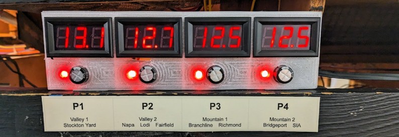
Category RandallRecently I was using a DIY “voltmeter car” to measure the NCE Boosters Voltage Levels. That’s how I found one of the boosters had the wrong voltage setting. I’m still getting sporadic reports of power loss in the mountain, and I ordered a RRampMeter to investigate this in more detail, yet in between I thought it would be nice to have an actual static display of the boosters’ voltage so I made this:
The design is fairly simple:
- 4x AC-DC Converters
- 4x DC Voltage Displays
- 1x 3d-printed case https://www.tinkercad.com/things/8XPdA7QdPjB-quad-display-voltage
The AC-DC Converters are fairly primitive: 4 diodes create a “full bridge rectifier”, and a little cap smoothes the output. That’s actually more than we need. We can see the capacitor sticking out in the design. Obviously we’re not rectifying AC -- the DCC signal is already a DC signal that just happens to swap polarity at roughly 8 kHz. And that works to our advantage -- it means once rectified, we get the “original” DC signal, minus the loss of the red LED. The cap here is mostly pointless yet should help smoothing out minor fluctuations when trains are running.
The DC Voltage Displays each have their own little adjustment, which I did not use. They seemed “good enough”, and I did not have a calibrated power supply to check their accuracy. I just did a quick check with my cheap voltmeter and it was in the 1/10th of volts range. It also helps that we don’t really care for the absolute voltage value here -- mostly we care about fluctuations or about wide changes.
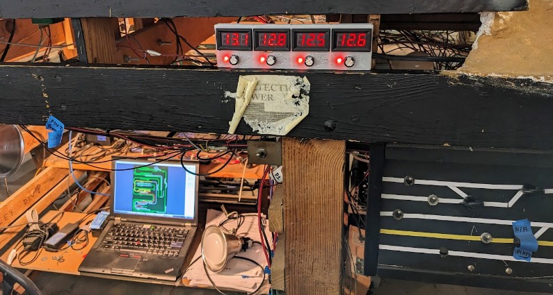
The power is measured at the output of the command station & boosters, before the NCE EB1 circuit breakers.
The first voltage P1, which is a bit different, is the one from the command station. The other ones are from the NCE PB5 boosters.
This is located just next to the computer / command station / boosters: