The Randall Museum in San Francisco hosts a large HO-scale model railroad. Created by the Golden Gate Model Railroad Club starting in 1961, the layout was donated to the Museum in 2015. Since then I have started automatizing trains running on the layout. I am also the model railroad maintainer. This blog describes various updates on the Randall Museum Model Railroad and I maintain a separate tech blog for all my electronics & software not directly related to Randall.
2024-11-24 - Napa Yard Turnout Power
Category RandallI was told yesterday that the turnouts in Napa Yard were inoperative. Now, that’s not a huge shock since last week I worked on the Richmond Panel and disconnected a couple unused DC track power leads. It would not be the first time that we find some totally unrelated connection between distant places on the layout.
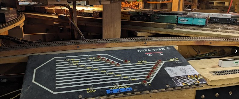
So let’s look at the Napa Yard:
Here’s what the panel looks like when we open it:
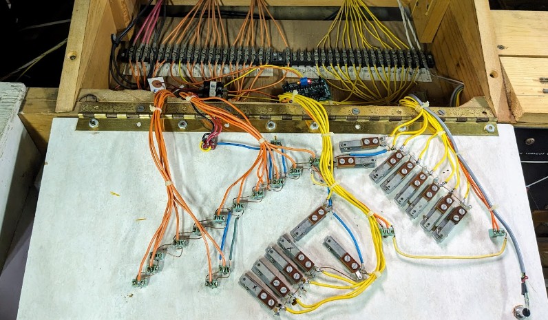
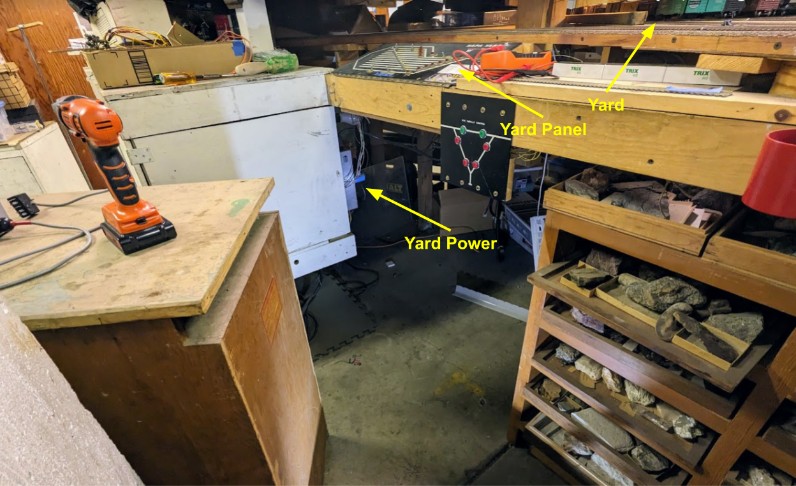
Upfront I can notice that the track power (orange wires) are separate from the turnout power (yellow wires). This is actually as it should be. So now “all” we have to do is follow the turnout wires. They are conveniently located under the layout and a bunch of things have been piled in front of them over the years, making access impossible. So first, I spent 10 minutes removing a cabinet, and before I could even do that I had to remove a couple unused DC equipment components:
The Napa Yard power panel is actually pretty neat, once I was able to crawl in the limited space under the layout:
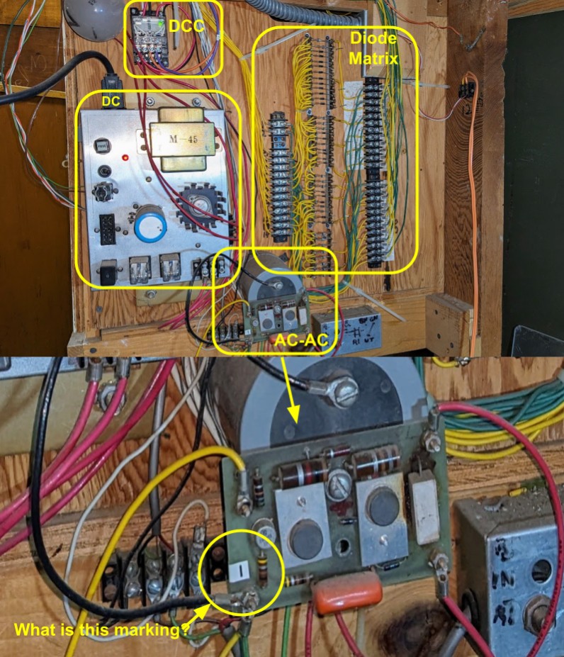
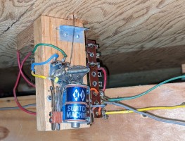
At the top we have the typical DC / DCC relay, then below we have the old-style “Mark II” power supply which was still powered. On the right we have the yard turnout ladder diode matrix. At the bottom we have the usual “super big capacitor with a basic AC-AC step down converter” which I find in many places on the layout. I couldn’t figure out what it is connected to (but that will change later below).
Although very neat to look at, I realize I just wasted 20 minutes accessing that stuff, because it is clear that power from the turnouts does not come from that panel at all. The big clue is that the yellow/green wires from the turnout diode matrix are not connected to anything on that panel. I originally thought maybe the big capacitor at the bottom would be involved, but nope, closer examination revealed it is not connected to that… or is it? Hard to say.
Since I had spent quite some time accessing that area, I took advantage of it to turn off the DC power supply that is doing nothing except contribute to global warming, and remove a couple unconnected lead wires that were just hanging bare on the floor. Random unlabeled wires laying on the floor, connected to nothing… these are usual lovely features of this layout. Not.
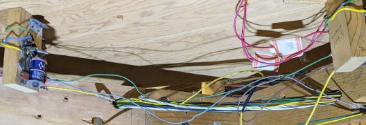
OK so after putting the cabinet back into place, let’s approach this from the other side and actually look at the turnouts for a clue of where they are powered from:
To be clear, I did start there yet I originally saw the mess of wires and thought nothing of them. Now, with some more background, I understand what’s happening with these twin-coils: the yellow / green wires are the power for the twin-coils, and the gray wire is actually the common. And in fact, upon closer inspection, all the turnouts gray wires are connected together and form a bus, which I then traced to this… “thing”:
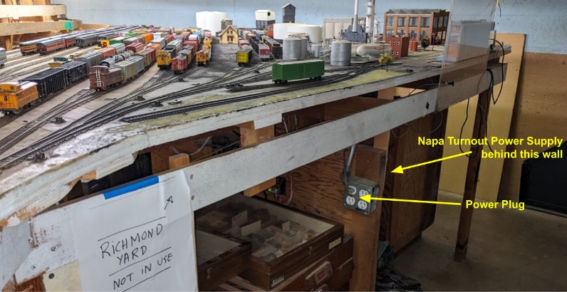
and that thing is located… under the Richmond Yard panel, where I was unplugging unused equipment last week!
So all I had to do to fix this was plug that gray power plug back in the outlet. I guess my initial suspicion was right. I disconnected this the previous week, wondering what it would affect, and now I know!
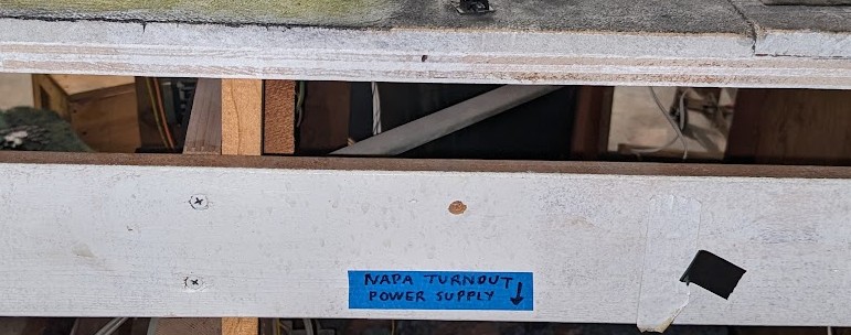
I take consolation that I now have a slightly better understanding of the turnout power in Napa, which will be very handy if we ever want to replace some of the turnouts. Orion and I considered replacing some of them. I added a much needed label on the panel and by the Richmond yard:
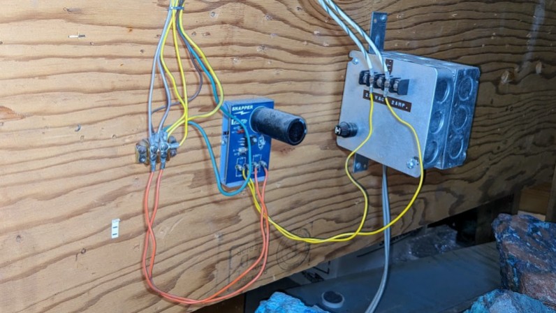
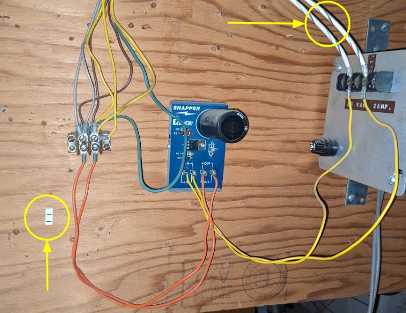
Looking at the turnout power, we can see a couple interesting things:
The 110 V plug powers a box labeled “25 V AC 2 AMP”. The yellow wires go to a Circuitron Snapper (PDF), and the orange output wires go to the turnouts “bus”: gray is the common to all turnouts, and yellow / green go to the diode matrix on the other panel. I have no idea what the two brown wires do.
I also take note of the two “white with blue” large wires that output from the 25 V AC transformer. These go to the other panel and power that super large capacitor, and I notice they both have that same label with a “I” mark. It’s still not clear to me what this large capacitor / power supply does on the Napa panel, but at least now I know where it is powered from.
I know that we have a spare Circuitron Snapper in the electrical cabinet. I should make a note on it to keep it and where it can be used.
That also means we cannot trivially swap these twin-coils by Tortoises without having a separate / parallel DC bus just for the Tortoises, as they are essentially incompatible with a Snapper.
