Model Train-related Notes Blog -- these are personal notes and musings on the subject of model train control, automation, electronics, or whatever I find interesting. I also have more posts in a blog dedicated to the maintenance of the Randall Museum Model Railroad.
2020-03-08 - Dwarf Signal for Turnout
Category DCC
Here’s an idealized turnout, showing the polarity of the frog based on whether the turnout is normal or reverse:
The frog is directly connected to rails A or B via the switch points of a slow-motion turnout motor, be it a Tortoise or a Fulgurex (in the case of the Randall layout). This works for any turnout which has a metal frog which polarity changes based on the turnout position. Examples are turnouts powered by a Tortoise or Fulgurex where the auxiliary contacts from the slow-motion motor are used to change the frog polarity. Another example are the EZ-Track turnouts with a metal frog.
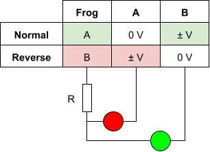
We can directly wire two LEDs, green and red, with a resistance, to the frog and the A / B rails to get them illuminated to indicate the position of the turnout, as follows:
When the turnout is in normal position, the frog is connected to the A rail, thus the voltage difference between the frog and A is zero; consequently the red LED would be turned off. However the difference between the frog and B rail would be the full DCC signal, and the green LED will be turned on. Similar thing when the turnout is in the reverse position, with the opposite LED being lit up.
Note that the LEDs would be directly connected via a resistor to the DCC signal, which is anywhere from 14-16 V “DC”. The DCC is a square signal with polarity inverted for each bit with roughly a 50% cycle, so essentially the LEDs will be conducting forward (illuminated) half of the time, and in reverse voltage (not illuminated) the other half of the time. That also means the polarity of the LEDs does not really matter in this case, however it is important to check the LED can stand the reverse voltage.
Red LEDs can supposedly stand a large reverse voltage whereas green / orange / blue ones cannot [citation needed]. A typical design workaround is to add another diode in reverse to the LED to avoid that reverse voltage.
A resistance is required in serie to compensate, anything from 1 kΩ to 10 kΩ depending on the desired brightness versus lifetime of the LED.

