Model Train-related Notes Blog -- these are personal notes and musings on the subject of model train control, automation, electronics, or whatever I find interesting. I also have more posts in a blog dedicated to the maintenance of the Randall Museum Model Railroad.
In Conductor 2, each route has its dedicated route type, driven by a “route manager”.
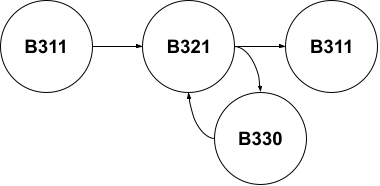
For our shuttle routes, we define an almost linear block list of blocks traveled.
- Normal: B311 → B321 → stop/reverse → B321 → B311.
As seen above, to handle the rare case of the end-run overrun, we want to actually have a block graph.
Click here to continue reading...
2022-01-22 - Conductor 2: Startup corrective behavior
Category Rtac
One of the potential benefits of route management in Conductor 2 is being able to fix the invalid start behavior. In conductor 1, we simply cannot start the mainline automation if the trains are not at the startup point. For the branch line, I do have some self correction.
Click here to continue reading...
2022-01-22 - Conductor 2: Error Management
Category Rtac
We need to dwell a bit more on error management in Conductor 2. What is the current situation, versus what we really want?
In Conductor 1, error management is made ad-hoc by the script. For each individual route (branchlines vs mainline), there’s a timer, and the goal is that each shuttle should complete its travel within 5 minutes. The implementation is rather simple: the timer is started when the engine starts in either direction, and stopped when the engine reaches the target block. If the timer expires, the global state is changed to error, which stops everything for that route. There is nothing in the script to get out of that error state. A manual reset (via the tablets) is necessary.
In Conductor 2, the error management should depend on the route manager. Here we’re only concerned with the shuttle “sequence” manager. We can decide to keep it as simple as it was in Conductor 1 -- namely that the route must complete in a given time.
Click here to continue reading...
2022-01-21 - Reboot on the Reboot on Conductor 2
Category Rtac
That Conductor 2 project has been taking too long now. I still think there are good ideas in the design and the core foundation for it. The implementation has been taking forever due to a lack of clarity combined with some other projects taking precedence.
In between I have started an implementation in Groovy which is not quite satisfactory. It was merely a prototype to explore the DSL syntax and as such the project structure has not been carefully planned. It’s already hard to extend and I realize I’m not able to express the script logic as I want with it. The core issue is that the prototype tried to do too many things -- explore how to create a Groovy DSL, figure out the language I need, and at the same time the business logic of the script. So I have a bit of everything, and nothing concrete for each category.
So let’s reboot it. Let’s tackle it differently. Ignore the syntax. Focus on what the script business logic needs to work. I can express that “on the paper” using the ANTLR script language from Conductor 1. I’ll figure the DSL and engine structure from there.
Click here to continue reading...
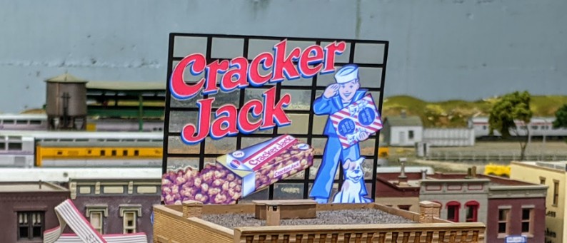
We’re in the process of adding a Miller Engineering animated sign on the layout, and later I want to revive the 2 broken ones (the theater one and the motel one). So naturally I wonder how they do work… What's the tech behind it?
Looking at the Miller Engineering site, they have an “experimental” section, which partially replies to that question:
https://microstru.com/collections/experimenter-kits
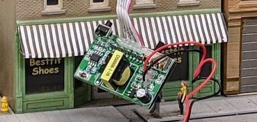
So these are listed as “electroluminescent” (a.k.a. EL) displays. The Miller ones come with a little control board, and they are typically powered by a 4.5 V DC power supply or 3 x AAA batteries. They call the board an “inverted”, and it features an obvious transformer, so that gives us a fairly good clue on what it does (i.e. that’s a voltage booster).
Click here to continue reading...
Today we’re modifying this cheap “Motion Sensor LED closet/night light”: https://amzn.to/3qqVBqS
So here’s the situation: the back room at Randall where we have the workbench presents some challenges. The switch to turn the room light is in one corner of the room, and we enter the opposite side of the room. And in between we have the Bridgeport yard, the Napa yard, and the workbench. Thus when we enter the room we need to carefully navigate around all these things mostly in the dark till we can turn on the light. Not ideal. Most of us use our phones as a flashlight to avoid tripping into something. Can we do better?
Click here to continue reading...
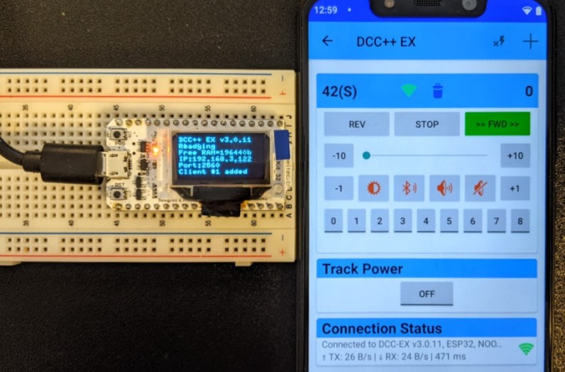
Today on the bench, we have two things going on:
On the left side, we have a “Wifi Kit 32” ESP32 running a fork of the latest DCC++ EX firmware.
On the right side, we have my Cab Engineer DCC Throttle app for Android communicating with the DC++ EX command station.
A few clarifications and explanations are needed here.
Click here to continue reading...
2020-03-15 - Dwarf Signal for Turnout, Continued
Category DCC
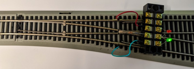
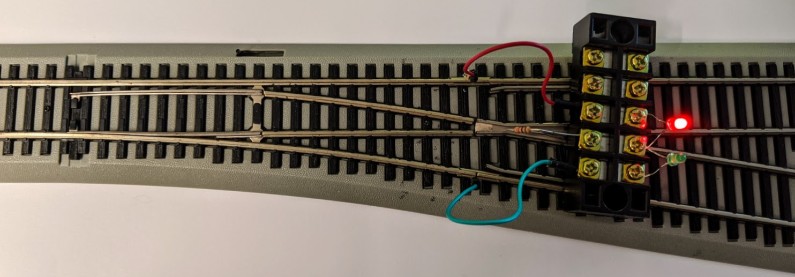
Here’s a concrete example that shows how to wire LEDs directly to a turnout frog, as explained here, and makes it obvious how trivial this is:
Resistance used here is 1 kΩ, that gives good brightness for both the green and red LEDs.
A 2.2 kΩ resistance also worked well enough for the red LED yet made the green one too dim.
In this example, the frog polarity is switched between rail A and B by a microswitch using the EZ-Track coil mechanism.
Another variation of this that I plan to use on the Randall Model Train layout is to only have the red LED, to make it clear when a turnout is left thrown/divergent. Especially for mainline turnouts, it acts as a “warning” signal. There is no need for the green LED in that case. I will likely embed the LED directly next to the turnout in the ballast. These LEDs are small enough that they could even be placed between the ties. The LED and the resistance can be wired to the existing terminal connected to the auxiliary contracts of the Tortoises.
2020-03-08 - Dwarf Signal for Turnout
Category DCC
Here’s an idealized turnout, showing the polarity of the frog based on whether the turnout is normal or reverse:
The frog is directly connected to rails A or B via the switch points of a slow-motion turnout motor, be it a Tortoise or a Fulgurex (in the case of the Randall layout). This works for any turnout which has a metal frog which polarity changes based on the turnout position. Examples are turnouts powered by a Tortoise or Fulgurex where the auxiliary contacts from the slow-motion motor are used to change the frog polarity. Another example are the EZ-Track turnouts with a metal frog.
We can directly wire two LEDs, green and red, with a resistance, to the frog and the A / B rails to get them illuminated to indicate the position of the turnout, as follows:
Click here to continue reading...
2019-09-29 - NCE AIU and NCE EB1 Circuit Breakers
Category NCE
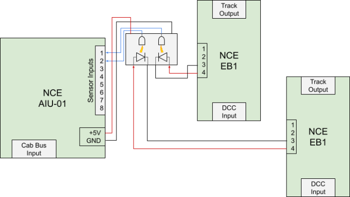
One issue I have on the Randall layout is that operators or automation sometimes short the layout. Then the NCE EB1 circuit breakers take over and of course shut down their corresponding power district. Then operators or staff ask me why things do not work, yet a lot of them fail to check the circuit breakers to see if they are shorting.
One idea I had a while ago was to use an NCE AIU01 to monitor the NCE EB1 circuit breakers. Then I could feed that into my automation software and get reporting of actual shorts right on my status web page.
The proposed solution is to use dual-channel optocouplers to connect the EB1 LED output to the AIU inputs.
Here are the details, as updated on 2020-02-04:
Click here to continue reading...
