Model Train-related Notes Blog -- these are personal notes and musings on the subject of model train control, automation, electronics, or whatever I find interesting. I also have more posts in a blog dedicated to the maintenance of the Randall Museum Model Railroad.
2021-07-04 - How do the Electroluminescent (EL) Displays Work?
Category TrainWe’re in the process of adding a Miller Engineering animated sign on the layout, and later I want to revive the 2 broken ones (the theater one and the motel one). So naturally I wonder how they do work… What's the tech behind it?
Looking at the Miller Engineering site, they have an “experimental” section, which partially replies to that question:
https://microstru.com/collections/experimenter-kits
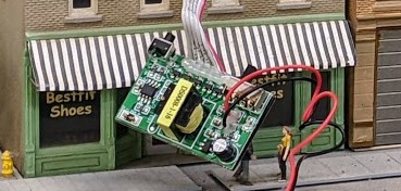
So these are listed as “electroluminescent” (a.k.a. EL) displays. The Miller ones come with a little control board, and they are typically powered by a 4.5 V DC power supply or 3 x AAA batteries. They call the board an “inverted”, and it features an obvious transformer, so that gives us a fairly good clue on what it does (i.e. that’s a voltage booster).
I could not find a direct example of how specifically Miller Engineering billboards sign work on the net. However there’s a similar thing called an “EL wire” which may be the same tech and is used for DIY purposes.
Adafruit has a pretty good technical description of the EL wire here: [Adafruit] Using EL Wire.
Another site I found explains how to build a DIY power supply for an EL wire: [Codrey] EL Wire Lamp Driver Inverter.
This explains these “EL wires” need a perfect AC (no DC component); they need a fairly high voltage (50-130V), and a frequency in the 60 Hz to 2 KHz range. The higher the voltage/frequency, the brighter they are (and the shorter they last).
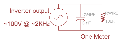
An important teaching from the Adafruit site is that the EL wire needs to be modeled as a capacitor with a resistance leakage:
(schema source: [Adafruit] Using EL Wire)
Using a longer wire just adds R-C components in parallel.
It also means the output cannot be measured without any load, and actually running the inverter without load may generate too high voltages that may damage the output transistors or transformer.
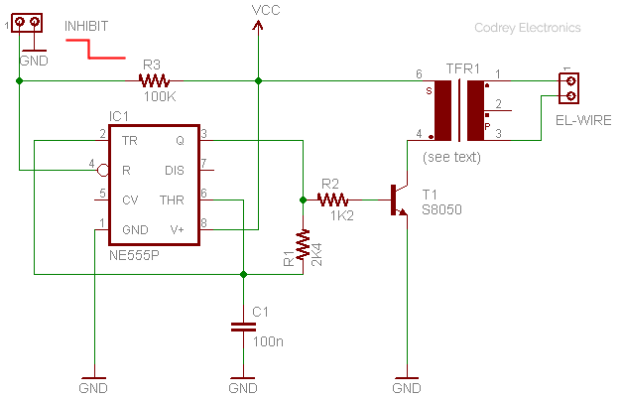
The Codrey web site has a schematic to build a DIY power supply. It uses an NE555 to make a 2 kHz driving a transistor and an audio transformer. Output voltage is not given, it is assumed around 100 V based on text.
(schema source: [Codrey] EL Wire Lamp Driver Inverter)
Which leads me to the Cracker Jack display at Randall or the “dead” motel / theater displays. I suspect on the theater and the motel sign that the display themselves are likely good, it’s probably the control board that died. On the motel sign I measured the power supply at 8 V instead of the expected 4.5 V.
I don’t have schematics for the Miller Engineering control board, but from a quick observation there’s an 8 pin microcontroller in there, the transformer to boost the voltage, and transistors to select which display elements get turned on. Which means I could hack one. Assuming it’s the microcontroller which died and the rest of the electronics is fine, I could control it using an arduino. That would be a fun thing to do with these two displays which are otherwise considered dead.
To be clear, I could likely “just” get some new control boards from Miller Engineering -- and I will likely end up doing just that as explained below. However in the meantime it would be interesting to learn and discover something new. Too many people want to just look at electronics as something obscure that no one should try to understand. On the contrary, there’s some value in looking at how things work, taking them apart and putting them back, and making mistakes in the process.
Edit: Then I ruined the display by mistakenly powering from 12 V instead of the 4.5 V power supply I was preparing. Yep totally my fault (well I did write “...and making mistakes in the process”, and I should add “and owning to them”). Now it does light up but only one segment and it’s not animating. Obviously I fried the 8-pin microcontroller, yet the part that drives the EL sine signal seems to be working just fine. I can manually trigger the output of the microcontroller and light the other segments. Which means there would be even more value in unsoldering that 8-pin microcontroller and driving the triacs manually. I’ve somewhat traced the control board and will post on that later.
But before that, I want to restate my philosophy. At Randall, I’m maintaining a layout in a public museum. I won’t be the maintainer forever, so it’s important to not leave hastily cryptic solutions behind. I’m fine with having fun hacking a Miller board and replacing their microcontroller by mine all for the fun & learning aspect of it, yet I also think from a maintenance perspective that is not the ideal thing. That’s why I want to favor off-the-shelf components when possible. My long term goal is that in N years when that billboard will stop working, someone will figure out what it is, and just hop on the Miller Engineering site and order a replacement for the control board if that’s what has failed. The more I customize it for my own fun, the less likely I am making that happen. Some folks are going to reply “yeah but in N years that tech will be obsolete, or the company won’t be there”. Maybe, that sure is possible, yet I’m not ready to make that assumption. It will at least be easier to figure out what the part is if it’s an off-the-shelf one than a custom made one.
Edit 2: For my own reference, Miller Engineering also sells replacement controllers right here.


