HO Rapido RDC SP 10 |
2017-01
Earlier this year I got the Budd RDC made by Rapido Trains, Southern Pacific #10 for the Randall Museum layout.
It’s a beautiful engine, with a great sound. They use a LokSound decoder with a iPhone 4-like sound speaker (the long type, not the sugar cubes ones).
One thing we wanted for the layout automation was to install a current keeper. ESU makes the PowerPack Mini, which should fit in there.
Table of content:
2 - Adding an ESU PowerPack Mini
1 - Shell Removal
First order of business was thus to find out how to remove the shell.
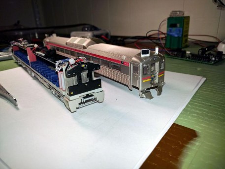
To open it: on a cradle, remove the coupler screw and pull the coupler box out. Repeat for both couplers. It all stayed together, which was nice.
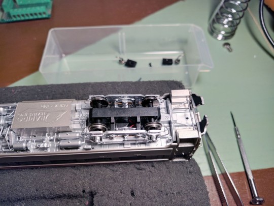
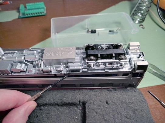
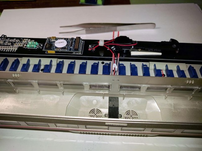
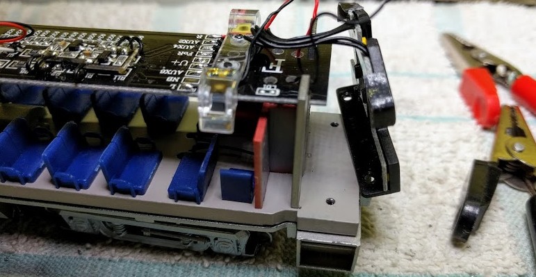
Approximately under the 3rd window on each side is a little plastic tab in the outer shell (see position indicated in the next picture). You'll need to pry the shell apart at that point, on all 4 sides. With a 5th hand, pull on extremities. I used the trick of leaving a coupler screw and pulling on that with some pliers, but after a while I realized it was almost easier to pull and rock the staircases out of the front and back shells, very slowly and extra careful not to break them.
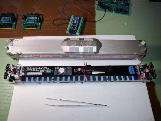
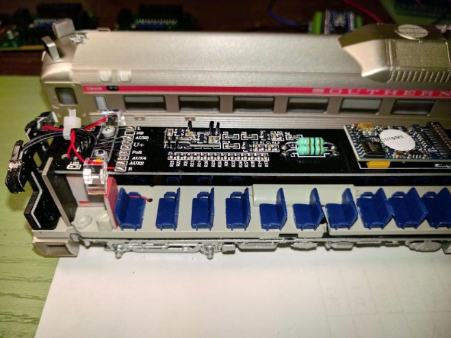
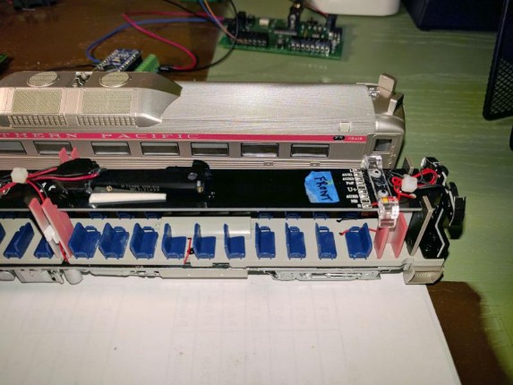
Once I got the shell out, I marked the front end immediately, but in fact it's not needed: in the outer shell casing there's a big F and R inside the roof, and on the mother board you can see FoF and FoR printed. Also as explained in the Rapido doc, the front is the one with the 5 windows and the rear with the 6 windows.
On this last picture you can see the little plastic tabs in the outer shell:
2 - Adding an ESU PowerPack Mini
Now let’s look at how to add the ESU PowerPack (a.k.a. current keeper) to the Rapido RDC SP-10. I’ve done it and after testing it I was really satisfied with the outcome, however there is a little important twist so I would like to explain how to do it.
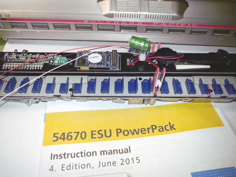
I used the ESU PowerPack Mini, which is that green capacitor as seen on the picture above, and there's more than enough space to add it in the RDC. It's a fairly easy install too.
First I had to open the shell, as explained above.
At first I was thinking of placing the keeper in the toilets (geez, these guys really model everything... there's got to be some kind of joke in there!) but the keeper was too large by just a millimeter. Oh well.
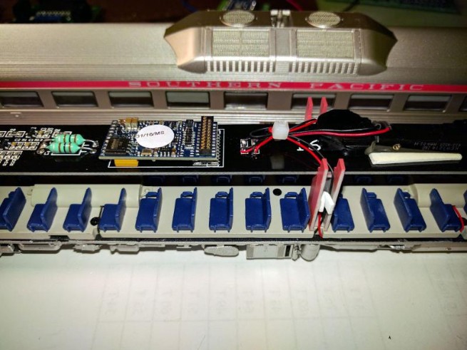
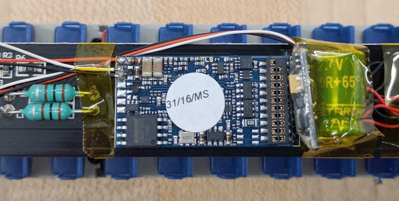
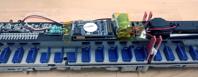
At the top, there's the long “motherboard” with the LokSound and in the middle there's a small bunch of red/black wires held by a tie. That location is right under the bulbous fans/exhaust ports and is the perfect spot to place the keeper.
So first the plastic tie had to go. I used a small screwdriver to untie it, or of course you can carefully cut it open. I then used some kapton tape to hold the wires in place.
Once I was satisfied with the location, I soldered the 3 wires to the decoder in the red/white/black orientation as indicated in the PowerPack manual. I had to borrow a Weller with a fine tip at work because my normal one looked gigantic next to the LokSound tiny solder pads.
Not the best looking job here, it looked better the first time I soldered them; oh well I'm never satisfied anyway; I checked it out for shorts and it came clean, that's what matter.
After I soldered the wires it occurred to me I could have trimmed them a bit. Some more kapton tape keeps everything tight in place.
Now here comes the little trick. I put everything on the track yet when I tried I couldn't get any effect from the keeper!
I redid the soldering to make sure, checked the red/black wires had power, made sure the CV 113 had a non-zero value, didn't matter, it clearly wasn't powering anything at all. Eventually I asked ESU for some insight.
So here's the trick, according to ESU, on this LokSound, AUX6 is shared between the AUX6 function and the white wire that activates the PowerPack. On this Rapido RDC, AUX6 is used for the rear ditch lights and the factory setting is for them to be programmed as Gyra Lights.
To use the PowerPack, the AUX6 function must be disabled:
- Using DecoderPro, go to the "Function Outputs" page and change "Aux6 Mode" from Gyra Light to Disabled.
- Using CVs: CV31 = 16, CV32 = 0, CV315 = 0.
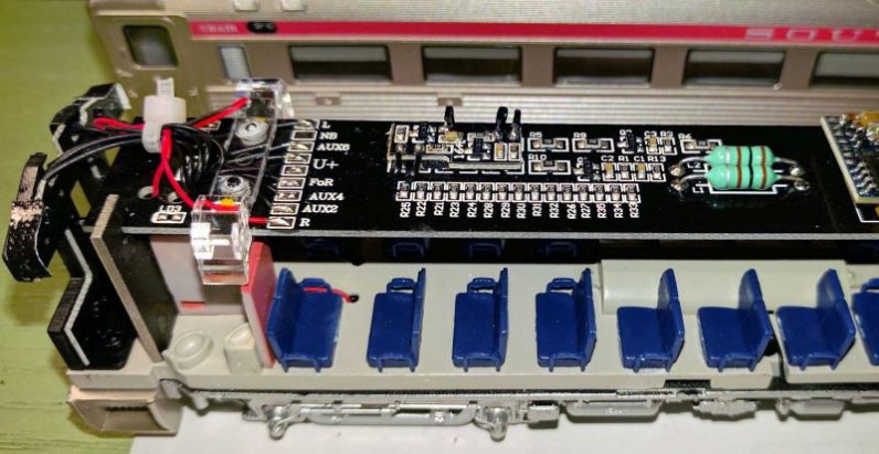
The issue I did notice is that when the AUX6 output is disabled, the rear ditch lights are then always on. It's barely visible on the SP-10, it only shows as a very faint light in the rear cab. I have not done it but an idea would be to unsolder the wire on the AUX6 pad on the motherboard, the second from the top as seen on this picture, with the advantage that it's easily reversible:
3- Accessing the Motors
First remove the shell as explained above. Then remove the screws holding the end boards in each “cab”:
Loosen the board, it is simply clipped in the middle red supports:
Finally the piece with the seats can be removed, there are 3 screws in the aisles (don’t forget the ones next to each bathroom!) and 2 above each motor:
Note that the “aisles” screws and the motor ones are not the same, so store them appropriately.
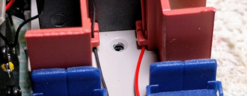
Pull the seats frame gently -- the red/black wires need to be “threaded” through, especially the ones around the motor covers. Also note that the pick up red/black wires are attached in the aisles next to the bathrooms:
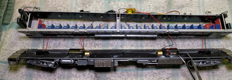
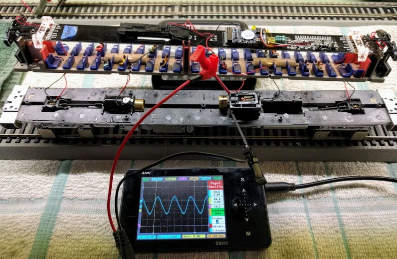
Finally we get to the motors and the drive axles:
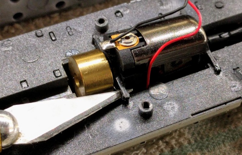
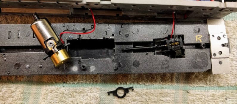
The original motors have supports that are glued with a bit of CA. Simply use a hobby knife to pull the supports up gently:
Original motor taken out, note how there are 2 supports, one stuck behind the flywheel and one that can move out:
4- Replacing the motors
Eventually the RDC at Randall stopped working. One truck was clearly not running anymore, at least not consistently. The symptom is that one truck runs fine, and the other one does not run at slow speed but sometimes runs at full speed.
First things first: if for some reason one or both of the original motors failed, contact Rapido’s support. It’s apparently a known issue in their first motor batch. Even trying to use contact cleaner such as CRC 2-26 on the collector did not fix the issue with mine.
They sent me new motors as well as new supports. The new supports are much easier to use than the previous ones, they clip on the motor frame.
Some tips from this blog post:
- “I can’t find the + side on the motor”. That was my main issue and I proceeded by elimination -- solder it and see if the motors turn in the right direction. For that I made a mark on the flywheel with a black marker on the original motors and made sure the new ones were turning in the same direction. I got one right and one wrong.
- ⇒ Turns out there is a “+” mark on the motor, on the vertical end wall next to the flywheel. It’s a very very tiny mark which I mistook for a scratch at first. It matches the red wire.
- Out of 4 new motors, one didn’t turn smoothly at all, and another one the flywheel was 1 mm too far and was rubbing against the plastic well. This was only apparent once the cover was screwed in place.
- Route the red/black wires and solder them in the direction that matches the cover with the seats. Otherwise they are not long enough to be routed back against the sides.
Reassembly is basically following the steps in reverse direction. It’s a tad tricky to put back the seats cover and pull all the red/black wires at the same time. Just go slowly and check the drive runs smoothly before and after screwing the seats cover.
This was also published in the MRH forums:
- http://model-railroad-hobbyist.com/node/29014 -- Shell Removal
- http://model-railroad-hobbyist.com/node/29098 -- PowerPack Mini
~~
~~
