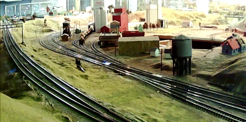
The Randall Museum in San Francisco hosts a large HO-scale model model railroad. Created by the Golden Gate Model Railroad Club starting in 1961, the layout was donated to the Museum in 2015. Since then I have started automatizing trains running on the layout. I am also the model railroad maintainer. This blog describes various updates on the Randall project and I maintain a separate blog for all my electronics not directly related to Randall.
2022-09-19 - Automation Updates
Category RandallThe automation runs 7 hours a day, 5 days a week. That's a lot of runtime for HO train engines which are not designed to run that much in their entire lifetime.
Consequently, for each mainline automated train, I have 2 similar engines with the goal of swapping them on a regular basis. I've done the UP engine a few times yet I have not rotated the Freight train engines in a while, and I finally got around to it today:
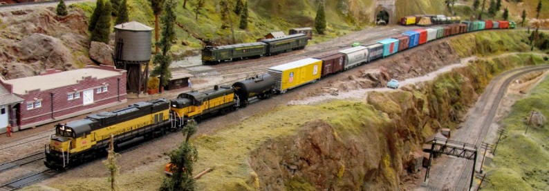
NS 1072 Heritage “Illinois Terminal” is back on Freight automation.
On the Branchline side, Santa Fe 804 has been behaving neatly and I just added a car and a caboose to it:
I'll need to carefully monitor that for the next few days to ensure this combo does not derail. The branch line track can be very finicky in a couple of specific places.
Allen and I started looking at what it would take to fix the mainline crossover T1-T2 in front of Stockton Station.
From my notes back from 2017, one side has a broken switch rail, and the other side has no power on the frog, and something in there was shorting when thrown.
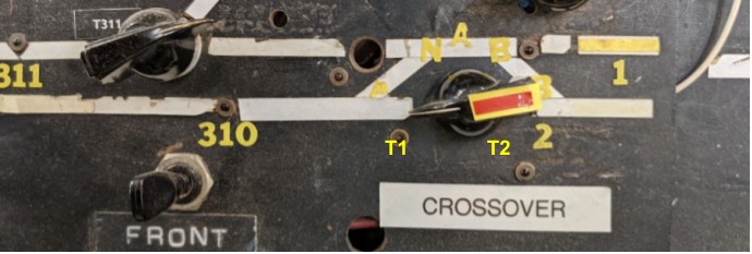
First, which is T1, and which one is T2? Turnouts on the Stockton Yard side go form T6 down to T3. Thus it makes sense the next one is T2 from the yard, followed by T1, away from the yard. I will need to label them on the layout fascia to remember that. I have an older track plan with the turnouts labels inverted, and then a newer one with them correct:
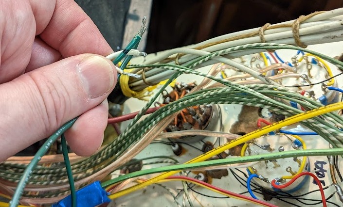
The toggle on the panel did not operate, and after a while I remember I had powered off the entire turnout panel because something was shorting all turnouts in there. And we don’t really use the panel, so fine, it’s basically unpowered. Looking behind, it’s quite a jungle in there:
Each time I open this panel, I want to tear apart all this mess and clean it up.
In that picture I’m holding the 2 wires for both T1 and T2. 2 green wires and 2 white ones. Each turnout has one green and one white, but which ones pair together? No clue. I took an educated guess at which 2 wires are likely to pair together and marked these with black marker, and of course I don’t know if that’s for T1 or T2.
I thus spend the next 15 minutes crawling under the layout trying to follow one of these wires. It was a bit of a painful chase as the wire went through a convoluted non-direct route starting in the opposite direction of the turnout!
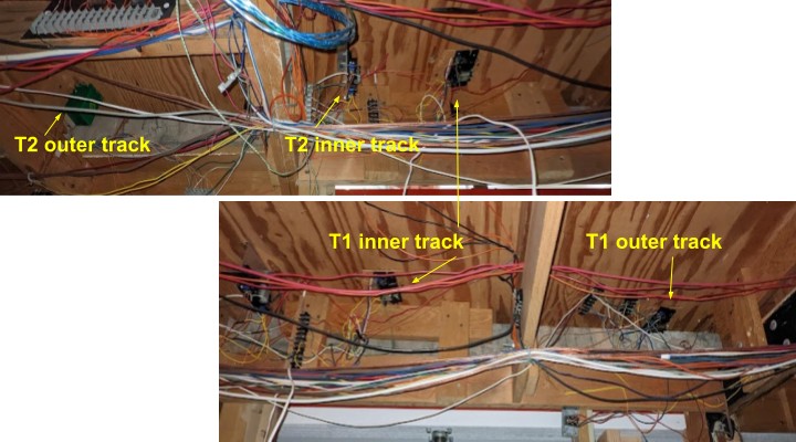
After a while I traced this to T2. Here’s what we have under the turnout:
The important data I needed to see here is that:
- T2 has one Tortoise (outer track) and one Fulgurex (inner track).
- T1 has 2 Fulgurex.
T2 is the one with the broken switch rail, which I don’t know how to fix, so we’ll put it aside.
T1 is the one I care most about. If I could get it to work, it would allow us to get out of the yard using the inner track and easily move to the outer track. Powering up the turnouts using the 2 green+white wires from the turnout panel did not do anything, so now I need to poke them in-situ with a 12 V power supply to verify whether the turnout motors actually work.
2022-09-11 - Photo Gallery
Category Randall
Spokane Portland & Seattle 4369 & 4070 (Alco C636 & RS-3) [photo Jim Evans]
A Pennsy passenger train with a GG-1 on the point at Stockton Station.
A few more PRR cars in storage on the Walong spur.
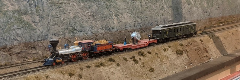
The Jupiter 4-4-0 and its search party has been spotted next to the Sultan tunnel.
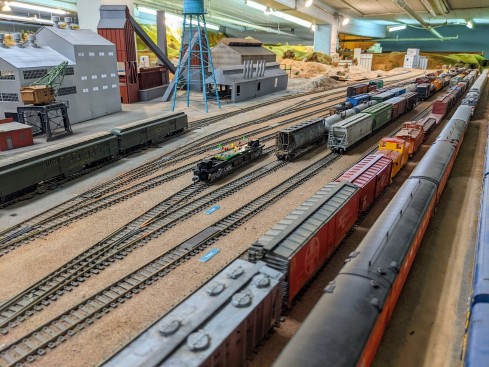
Here’s the result of an afternoon of work with Allen:
What you do not see here are the little blue tape markers that were condemning some of the yard tracks since 2017 and 2018. More on that below.
First I’ve reworked my DCC Dead Spot Detection Car, and it’s worth explaining what I did to fix its electrical pickup issues.
Click here to continue reading...
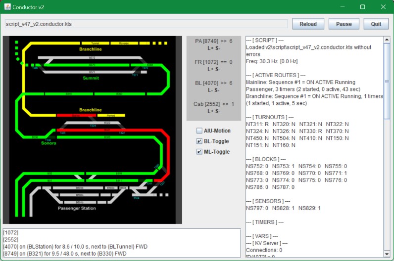
I’ve spent the last couple months mostly working on a new version of my automation software: Conductor 2. The new version has an entire new scripting language, advanced logic for block handling, and a simulator.
It’s almost ready for trial at the museum. For now, it works neatly using the simulator:
I have detailed updates about Conductor 2 on the technical blog here.
I also have updated RTAC, the Android software that runs on the tablets at Randall. These are mostly little implementation technical details, and not directly visible to the visitors. The latest version of RTAC is now available on the Google Play store.
Back in May, I was very happy to have placed this SP&S Alco RS-3 #4070 on the Branchline. What’s not to love about it, it’s an RS-3, and the Portland scheme is gorgeous, and it had a matching caboose with directional marker lights.
Eventually last week it just stopped working. But oddly enough, it stopped working just on the Branchline. The same engine works well when directly addressed on the programming track or on the Mainline, but then once on the Branchline, all I get is sound and no movement. That’s… puzzling.
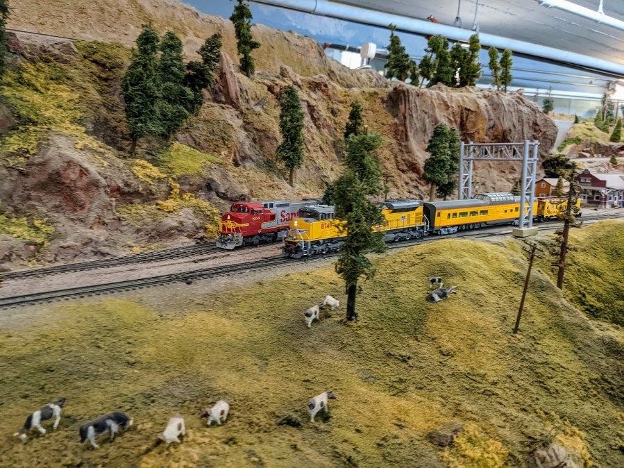
Instead I picked up that Santa Fe 804 engine I had been using for track cleaning. It works well. Tested it on the Branchline and it survived the very finicky track. Here’s a nice shot where the automation train was reaching the branchline line. Compare with real pictures of the GE C40-8W ATSF #804 vs the EMD SD70ACe UP #8749.
I’m amazed 804 can navigate that track without falling all over itself. It’s quite a remarkable model. I love it.
Click here to continue reading...
2022-06-23 - Misc Maintenance
Category RandallI've completed a lot of small maintenance items recently. Well, some were maybe small yet took several days to complete.
I’ve run the track cleaning train today. Jim usually run these Santa Fe F units in tandem, however they don’t match properly when coupled together:
Instead I got one of the old units from GGMRC and I made up this track cleaning train:
Santa Fe #804 still runs nice and strong. I don’t have enough pulling power with one engine for the two pad cars so I had to remove the silver DRGW one. On the roller, I put 2 drops of automatic transmission fluid (ATF) per rail, followed by the pad car.
Jim has some Rail-Zip there so I thought about using that then I noticed this old trainsorders thread basically indicating that Rail-Zip is similar to that ATF we have been using for years. I guess at least the form factor in the little bottle is more convenient.
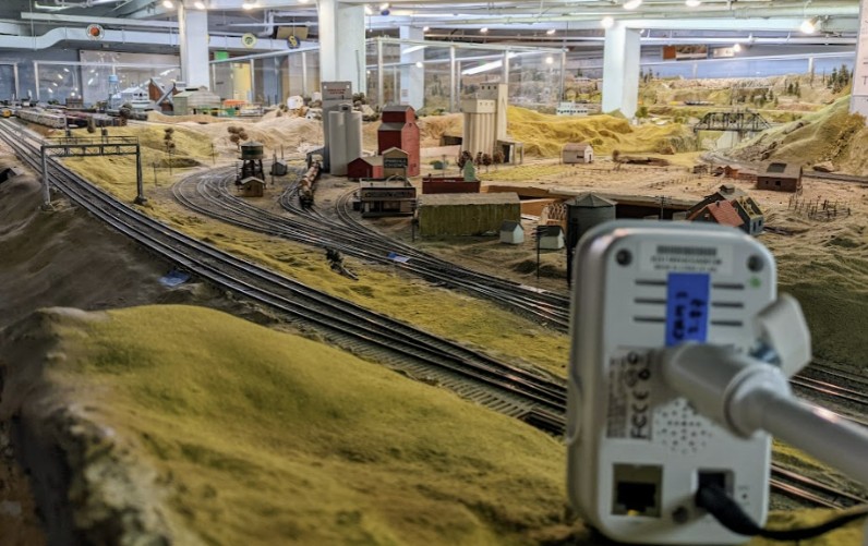
Since the last past, I’ve also reworked the support for the Edimax IC-3116W 720p cam for the Train Vision Project by Lodi:
Over the last few days, I’ve spent a lot more time than I expected updating the various Wyze cameras. For some reason, half of them had lost their detection settings. I simply dislike the current Wyze seemingly redundant subscription levels with the Cam Plus, Cam Plus Pro, Cam Plus Lite, and Cam Plus Super Ultra Ultimate Whatever confusion mess. It makes it annoyingly complicated to set up these cameras because the app is really pretty inconsistent and various settings need to be adjusted in different screens.
As I’ve been saying for a while, I can’t take the Wyze cams seriously -- it’s ok for the casual usage we have here, but they definitely do not have a serious security camera ecosystem.
Their sdcard storage is basically pointless. My first V1 cam stopped working (or more exactly: it works but can’t connect to the wifi anymore so ¯\_(ツ)_/¯ ). One of the V3 keeps stopping (I have a theory that it is too close to a fluorescent light fixture). Most of the cams eventually freeze up randomly (which I somewhat solve by forcing them to reboot daily).
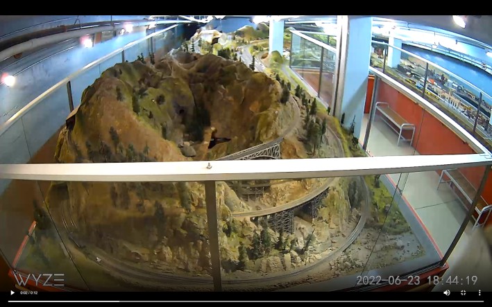
Finally, since I have a spare Wyze V2 Cam, I’m trying an alternate view from Sultan. This is the angle I have so far:
We’ll see if that works. As usual my goal is not to see the museum visitors and instead I’m mostly interested in monitoring the train automation or the Saturday operators' trains. Ironically it’s hard to get a view where people are not in the picture.
As with the other Wyze cams, the quality of the recorded videos is very compressed, yet it's enough to see if a train is stopped on the track where it should not be.
This view angle is not bad except we can’t see the branchline bridge which is obscured by the white window support, so I might move the camera a bit to the right after I get an extension cord.
I’m continuing trying alternate views for the cameras for the Train Vision Project. This time I’m still using the same good ol’ Edimax IC-3116W 720p cams I had around from 2015. They work well, and have the added benefit of having an ethernet plug so I can transfer the video over wired ethernet instead of saturating the limited wifi bandwidth.
This time I’m trying to change the Valley camera. In the initial project phase, I temporarily placed the camera by Fairfield, mostly because it was easy to access and we had a view of the automation trains -- which was an excellent tool to configure the Train Vision Project. Yet that was merely a placeholder. The real goal of the project is to provide a view of the layout that visitors cannot readily see from their public view area. One such area is the top of the mountain -- covered in the previous blog post -- and another such area is the Lodi town in the back.
Here’s one such attempt:
And viewed from the Vision laptop screen, this is the lower right quadrant:
Click here to continue reading...
I got a new camera for the Train Vision Project. The current ones I’m using are refurb Edimax IC-3116W 720p cams I had around from 2015. They work well however they are quite bulky.
The new one I’m trying is a small TP-Link Tapo C110. It’s a 1080p no-frills camera which I run at 720p. I particularly choose these since they have official RTSP support, which in layman terms means the laptop can grab the video feed from the camera directly over the local wifi without involving a remote server. The camera is fairly small and light and setting it up with the TP-Link Tapo phone app was a breeze.
In the Train Vision project, one thing I wanted was to have a view from the top of the mountain and one from the Lodi area -- two areas where visitors cannot readily see the tracks right now. I do have the Edimax cams setup next to the visitor area as a placeholder but these don’t add a lot of value since these are areas the visitors can already trivially watch. The point is to highlight parts of the layout out of view from visitors, and that’s where having a smaller lighter camera that I can blend in with the scenery comes in.
I’m experimenting with a view from the top of the mountain:
Here’s the view from up there:
Click here to continue reading...
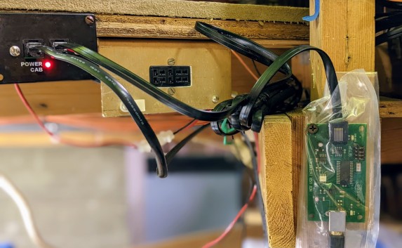
I installed a new NCE USB Interface for the JMRI laptop on the workbench. The last one got wet during the last rainstorm and I wasn’t able to revive it. The new one is wrapped in a little plastic wrapper to hopefully prevent it getting taunted a second time.
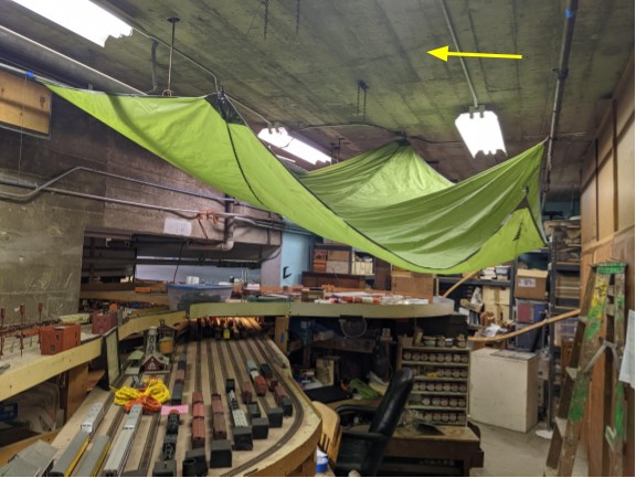
To help against the next rain season, Allen and I reorganized the protective tarp on the ceiling. The arrow highlights the source of the leak from the concrete ceiling. It is a small dripping leak, yet persistent enough to do damage to the wood workbench and all the equipment.
Not pictured here, we have a large bucket at the front that collects dripping water.
And yes the museum direction is well aware of the core issue. That’s how we got the tarp to begin with, as that imaginative yet hopefully temporary solution was installed by one of the museum coordinators while we wait for official repairs to happen.


