Model Train-related Notes Blog -- these are personal notes and musings on the subject of model train control, automation, electronics, or whatever I find interesting. I also have more posts in a blog dedicated to the maintenance of the Randall Museum Model Railroad.
2018-12-08 - Conductor 2: Route Sequences
Category Rtac
Above I mentioned the key features for Conductor 2 would be profiles, configuration language, and routes.
I should elaborate a bit on this, especially the routes.
First the profiles: A profile is simply a DCC address number and a map of variables values. Routes will define variables for, e.g., timers and speeds. The profile will fill in these values to adjust them to a specific train.
Click here to continue reading...
2018-12-01 - SQ12 Mini Camera for Cab Rides
Category Video
I’ve been doing all my “cab ride” recordings using a Mobius Action Cam. A few months ago I tried the RunCam 2 for comparison.
This time I decided to try one of the SQ “mini” cameras series for a change.
Cab ride filmed using SQ12 Camera
I got this SQ12 from Amazon:
Click here to continue reading...
2018-10-12 - CMRS Touch Panels, continued
Category CMRS
This is a follow up on that proof-of-concept I made at CMRS about touch panels for the mainline.
I'd like to elaborate a few points, with some pros and cons, which I had been thinking about when I started the project. Upfront I want to make it clear I am not advocating for one solution or another. I am offering "food for thoughts", pros and cons, and matters of discussion. Some of the discussion involves industries or city names which are specific to CMRS’ layout. A map of it can be found in the link above.
Click here to continue reading...
A lot of my interests when it comes to model train layouts are all about automation. Automation can mean to make the trains move automatically but it can also mean to automate signaling -- displaying semaphores and search lights according to traffic on the layout. The common denominator for both is block occupancy detection, namely to know where trains are on the layout.
An early prototype of camera-based block detection
Click here to continue reading...
2018-09-15 - NCE AIU01 and Motion Sensor
Category NCE
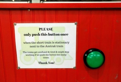
As previously discussed, on the Randall layout, visitors press a button to trigger the trains’ automated sequence. Soon enough, we added a sign asking people to be nice with that button. The sign has nothing to do with the actual electronics behind nor the automation, not even the button itself. Both the button and the software are sturdy enough to survive any abuse.
And abuse there is. The abuse is simply… social. Kids hammer that button like there’s no tomorrow. Does it make trains run faster or more frequently? Nope. One would hope it would be a good exercise in parenting in teaching kids to be reasonable and treat common property adequately, but alas, no.
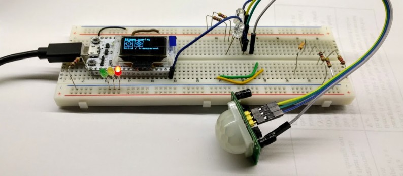
Eventually Jim and I had enough of it and I decided we could simply use a motion sensor as a trigger instead of a hardware button. Back in March, I built this prototype:
The original design for the motion sensor was to use an ESP32 with an HC-SR501. The ESP32 would be used to send a sensor activation command to JMRI.
Click here to continue reading...
2018-09-02 - Digispark Tiny
Category Arduino
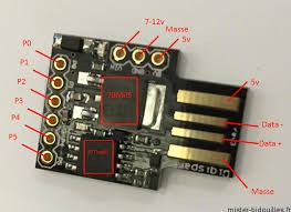
The Digispark Tiny is probably the most basic and compact Arduino-like I’ve worked with. It’s about the size of an USB A plug. It is powered by an ATTiny85 and offers 1-5 I/Os depending on usage (typically 2-3).
(image source: mister-bidouilles.fr)
Kickstarter Date: 2014.
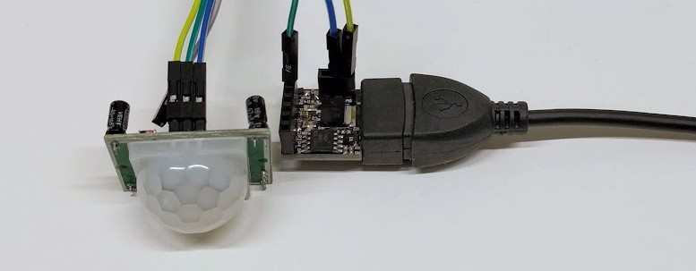
Example of the Digispark Tiny connected to an USB OTG with a PIR sensor:
Click here to continue reading...
2018-09-01 - Conductor 1 and E-Stop
Category Rtac
Another behavior I need right now in Conductor is to have an E-Stop feature when trains get blocked. It’s the 3rd time a train keeps running for an hour or more and is blocked somewhere. Ideally Conductor 2 would have a model of “what’s next” and error management, but I can’t wait for that.
What I need is simple: a route starts, and if the train has not reached the destination in say 10 minutes, send a stop to the train. We can do that trivially using a timer, which is canceled (aka “timer end”) when the train reaches its destination.
Although not exposed through the script grammar, JmriThrottleAdapter (.py) and IJmriThrottle (.java) do have an eStop() method (the estop is only used when triggering an e-stop via RTAC). Right now just using a repeated stop should be enough.
Click here to continue reading...
2018-08-27 - Meanwhile in Conductor 1…
Category Rtac
Conductor 2 is nowhere ready and I need changes now so they go in Conductor 1.
The desired next step is to support the presence-based activation rather than button activation.
Although I have plans for a Conductor 2 which would be route-based, at that point this is an orthogonal task and it can be deferred for later.
Profiles is a Conductor 2 feature, and not tied to a presence sensor.
What is the minimum “clean” approach needed for the sensor presence?
What is the minimum I need to provide?
Click here to continue reading...
2018-08-18 - An update for Conductor 2
Category Rtac
Several angles of discussion for Conductor 2.
First config file. Drop the ANTLR language. Don’t do a DSL using Groovy/Kotlin. Instead let’s keep it simple and use a Jython-based config file (like BUILD files). Sure it won’t be as eye candy as a gradle-like DSL but it might be easier to create and get started.
Example of “pythonizing” the current Conductor 1 script:
B320 = sensor(“B320”, “NS784”) T320 = turnout(“T320”, “NT320”)
PA = route(“Passenger Automation”, blocks=[B310, T310, T320, B320, T330, B330, B340, B350, B360, T371, B370], speed_vars=[“mainline”, “station”, “sonora”]) PA.on(B320, delay=10, events=[PA.throttle.speed(5), PA.throttle.horn()])
profile(“RDC”, route=PA, speed_vars={ “mainline”=20, “station”=8 }, …) |
This is obviously more verbose. There’s a need to carefully stringify arguments and build lists or dicts where needed. However at that point it’s just about building an API, and there’s one benefit in having typed variables (e.g. a sensor var can’t be used where a turnout is used, etc.)
Click here to continue reading...
2018-05-20 - Signal quality in Advanced Tomato
Category Misc
I’ll just leave this here for those who use Advanced Tomato on their wifi routers: the “Quality (%)” column in the Device List is not a percentage at all. It’s just a delta from the client’s RSSI to the interface floor noise in dBm.
From https://github.com/Jackysi/advancedtomato-gui/blob/RT-N/status-devices.asp, line 248:
