The Randall Museum in San Francisco hosts a large HO-scale model railroad. Created by the Golden Gate Model Railroad Club starting in 1961, the layout was donated to the Museum in 2015. Since then I have started automatizing trains running on the layout. I am also the model railroad maintainer. This blog describes various updates on the Randall Museum Model Railroad and I maintain a separate tech blog for all my electronics & software not directly related to Randall.
I’ve done some work on the Vision computer to get more reliable networking. The USB-to-ethernet adapter hasn’t been behaving as stable as I’d like to, and I fixed the wifi so at least I got that.
But maybe it’s not just that USB-to-ethernet adapter that needs some more work though -- last time I went by the museum, all the port lights were off on the ethernet switch till I power-cycled it so maybe I should look at that first.
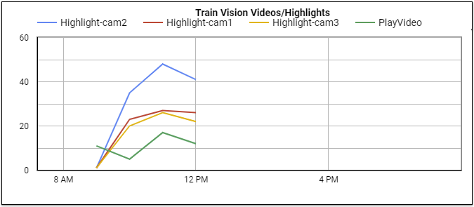
I have also updated the highlighter’s logic in vision, and actually I like the updated logic even less than the original. Look at these stats:
That’s terrible. Too many highlights. The thing is too sensitive, I need to change it to have some kind of adaptive threshold. Some of the highlights happen when no trains are moving, probably because the RTSP h264 stream is of subpar quality and very noisy, not to mention noticeable inconsistent frame rate. That’s why I need that wired ethernet to work.
And what’s up with the lack of stats after noon? I know the laptop was running at least till 4-5 pm. If it were a 12/24 hour mismatch, the “12 pm” events should look like midnight (12 am) and the 4-5pm events should look like 4-5am, which is not the case here. More mysteries.
A few things have happened this week-end.
First the visible yet inconsequential thing: the Bridgeport Ballon Track #2 now has the proper Auto-Reverser.
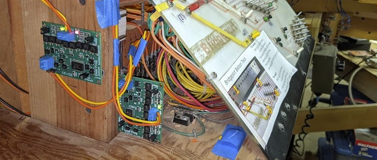
The story about this is that I had ordered two Tam Valley Dual Frog Juicers to be installed and configured as auto-reversers, one per balloon track. Unfortunately in the order I was sent a DCC Hex Frog Juicer by mistake. The Dual Frog Juicers can use up to 4 amps per track, whereas the Hex Frog Juicer can only only 1 amp per track and that’s not enough when running multiple engines in consist with sound. So now I just got around to installing the proper board. It was a rather trivial swap since I had done all the prep work when installing the Hex Frog Juicer, so really only terminals to unscrew/rescrew. Probably took more time to take the pictures and write this post than actually installing the board. But hey, one more task is complete on my long list.
The more exciting news is that I got around to update my Layout Presentation Documentation. I know, exciting, isn’t it? “See? Nobody cares.” Well I do. I added a whole chapter on the computer setup used in the “train room exhibit”, and updated the pending work list, and I think that’s pretty neat. I’ve also updated the Known Issues list.
Click here to continue reading...
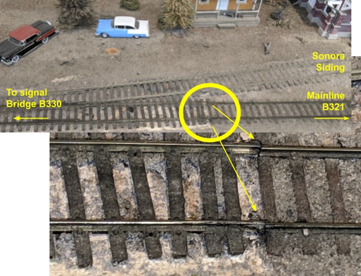
Speaking of disasters waiting to happen, this is the mainline track at T330 Sonora:
What we can observe here is that both rails from the turnout lead are not soldered to the mainline track anymore. There’s some remnant of solder, thus I’ll venture a guess they used to be joined. Moreover the track lifts by about half a millimeter and can flex up and down freely. It’s amazing we don’t derail here. And that’s the mainline where every single train runs..
Affected |
Mainline B321 close to Turnout T322. |
Description |
Dead spot on Mainline B321. |
Summary Fix |
Fix bad track joiner. |
Description of Issue
As explained earlier, we’ve been having issues with the train stopping on a dead spot on the mainline block B321, just after the Branchline turnout T322. I posited the issue was a broken solder joint, and it was indeed the case. A repair has been made -- actually two of them --, we’ll see if that holds.
On the track schematics, repairs were performed at the approximate locations shown below, on the red-side rail.
Trains used to stop dead in that area recently, intermittently. Typically that’s due to a solder joint that is broken and now makes a bad contact. As the track shrinks or expands with humidity, temperature, and the weight of the rolling stock, contact can appear or vanish during the day. The test was simple: with the train dead at that spot, just putting some slight pressure on the track was enough to power the train again. Problem is, that track has been naturally weathered by decades of usage, and it’s nearly impossible to know where the solder joints are, or for what. There can be many, from track feeders, to rail jointers. Not to mention the voluntary block isolation gaps that I need to preserve. Due to the lack of documentation, it means that when I find a gap (or a broken rail that looks like a gap), I don’t really know if it’s on purpose or not.
Description of Fix
First repair at spot #1 was done somewhere near the middle of the block. There is a track feeder under the layout going to both the black and red rail. It’s worth pointing two important details at this point:
Click here to continue reading...
2021-11-14 - Motion Sensor
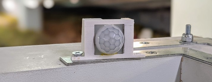
Category RandallThe motion sensor finally has a little cover to keep it in place:
Description of the Motion Sensor and how it is hooked into the NCE AIU01:
https://www.alfray.com/trains/randall/about.html#h.mnaglpwxrgon
For reference, here’s how the sensor is calibrated:
Click here to continue reading...
Recently a dead spot has developed on the mainline track #1 just in front of Stockton Station.
And last week we had another one: the automation trains are stopping on the mainline between the Branchline Interchange and the Sonora turnout.
As with (the one) previous short we had on the mainline, this one is intermittent, which makes it so fun to find and debug. It works for a while and then suddenly stops. That’s the typical sign of a cold / broken solder joint that moves during the day as the rail expands or shrinks with humidity or temperature. So now I have to look for a solder joint. Could be a track feeder, or it could be a rail joiner, who knows.
The “nice” thing is that I can temporarily fix the dead short just by pressing on the outer rail. So that gives me a clue...
Click here to continue reading...
2021-11-09 - Rain
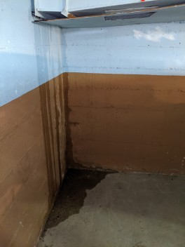
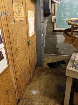
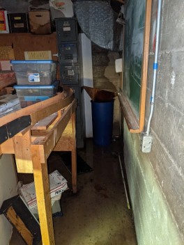
Category RandallIt’s been raining. And we’ve been reminded the joy of being in a basement:
There’s a full inch of water on the floor. Not exactly a novelty, although when it happened a couple years ago it was supposed to have been taken care of.
The new addition is that water is also dripping on the Napa yard; we guess it comes from the ceiling:
Click here to continue reading...
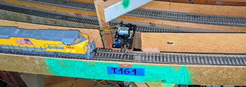
Affected |
Turnout T161 (end of siding between Bridgeport & Sultan). |
Description |
Intermittent loss of power on frog. |
Summary Fix |
Deactivate turnout (always straight). Bypass the frog polarity contact/inverted. |
Description of Issue
Back in 2018, we had engines stop-and-go on turnout T161 for quite a while, especially steam engines, or short non-MU engines. The turnout was always in the normal position when this happened. Back then, it was determined the frog power routing on the Fulgurex created a resistance. This was solved in 2018-12-12 by replacing the Fulgurex. The issue re-appeared recently.
Click here to continue reading...
2021-10-10 - Train Vision Update
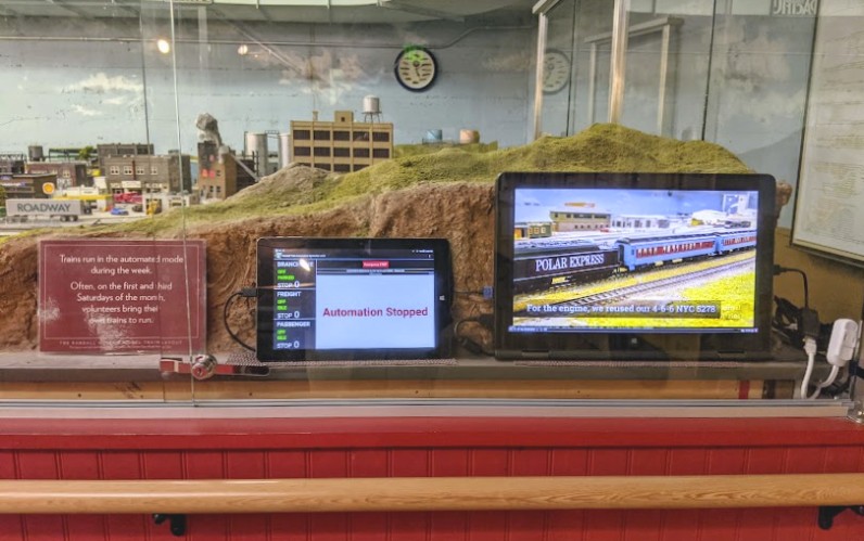
Category RandallThe “Train Vision” project uses my custom Vision software running on a laptop, displaying pre-recorded videos I made of trains running on the layout, mixed with live views of trains actually running on the layout.
All the videos come from my Youtube Channel playlist for the museum. I have a couple news train videos to add to that list: an SP Daylight, an Amtrak Superliner, and an SP Cotton Belt. Interestingly since I’ve recently switched to doing shorter videos in the 3-minute range, that works actually better for that kind of display.
One thing I’m particularly proud of is what is not visible here: this runs on a Lenovo Yoga 15 laptop folded over. It provides a good sizable display although it’s not huge so it doesn’t dwarf the layout. This runs the latest Debian Linux distro, and I have spent a lot of time ensuring it powers up automatically with the layout. All the museum staff have to do is turn on power to the exhibit room in the morning, and they don’t have to specifically deal with that computer. Same when they close in the evening. All automated, as it should be. Of course it’s an automation which means sooner or later it will fail to start and it will require manual intervention, however that will be newsworthy because it will be the exception rather than the norm.
This has been running for a couple weeks now and is performing fairly well. Based on my observations:
- Although some viewers get it instantly, some others are confused on which video shows a live view vs a recorded one. I already added a blinking “Live” sticker to the live views. I’ll follow up by adding a “Recorded” banner on the recorded videos. I’m thinking of a generic “play” triangle icon + record date + title.
- Originally my first prototype was streaming videos directly off my Youtube Channel playlist. I thought that would be a concern as the recorded videos would stop playing if the wifi was not cooperating. Thus I switched to downloading all the videos and playing them off the drive. Glad I did that because the first week the wifi was really sub-par at the museum although it seems to have somewhat improved since. I have a script I can run that will update my playing list using youtube-dl to download my own videos locally, so updating the playlist is still fairly easy.
- One thing I do look forward to is working with Tiffany from the Randall Museum Friends to make the display customizable for special events. Says they host a gala or some kind of social event, we can have the software download one or more mp4 (or a private youtube playlist) and play it specifically for that day & time slot.
The last item on the list is the quality of the live video feeds from the cameras on the layout. I was having some terrible frame rates over wireless, with some obvious mp4 dropped frame artifacts. I switched one of the cameras from wireless to wired ethernet, and I also switched the laptop to wired ethernet using a Linux-compatible Cable Matters USB to Ethernet Adapter (linux pro-tip: this one requires an apt install firmware-realtek from Debian 11 “bullseye”). That combination brought me the stable 15 fps I was looking for. I will wire the other two cameras once I have them in their final location.
Time for more maintenance. This time I adjusted the grade crossing light sensitivity with some room lights off, and it seemed to go better. In this case I had the fluorescent lights off, the single center spot on, and the side spots (by the walls) on medium.
More importantly we had an interesting case: a turnout malfunctioned on the Bridgeport lead track.
That seems innocuous except this somehow shorted the B450 block on the mainline (the one that leads to Bridgeport) on the Mountain Panel 2, and it also made blocks B330 and B360 seem occupied on the Mountain Panel 1 -- these two blocks are used by the automation and since the track appeared occupied the automated trains would not start. It did take me some time to figure all that out since I started in reverse (why the blocks seemed occupied) and I had to trace it back to the short on the other panel and then to the Bridgeport lead. I still don’t have a full explanation here. It just doesn’t quite make sense.
Anyhow, this is what I found on the Bridgeport lead:
What’s wrong with the point?
Click here to continue reading...
