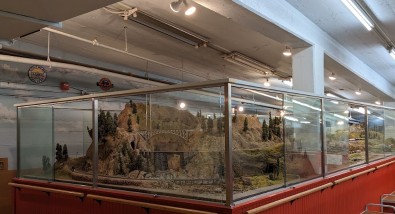
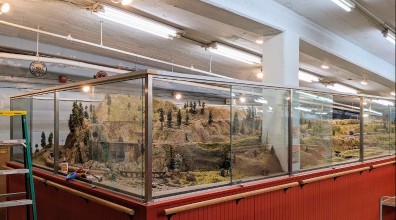
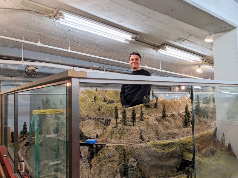
The Randall Museum in San Francisco hosts a large HO-scale model model railroad. Created by the Golden Gate Model Railroad Club starting in 1961, the layout was donated to the Museum in 2015. Since then I have started automatizing trains running on the layout. I am also the model railroad maintainer. This blog describes various updates on the Randall project and I maintain a separate blog for all my electronics not directly related to Randall.
The turnout T324 on the branchline has multiple issues.
One of them is that clearly the contacts on the Circuitron Tortoise Slow-Motion Switch Machine do not work as expected.
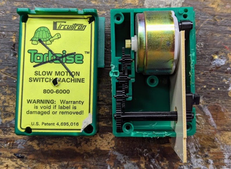
So what’s inside a Tortoise?
It turns out that it’s quite easy to open once you figure that the screws are “hidden” under the label. No need to force the plastic as I unfortunately started doing first.
I guess the warranty is void now… What warranty anyway? That switch machine is likely 10 years old or more -- every single Tortoise on the Randall Model Train Railroad was installed by the GGMRC members and thus that had to be before 2015. According to the “recent changes” on the Tortoise page, the tan color of the circuit board indicates a unit built before 2019.
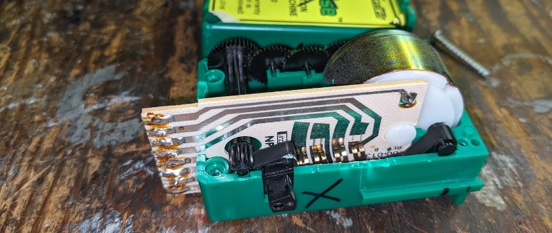
The auxiliary contacts are simply printed on a small motherboard on the side:
Originally I wrote this off entirely, but now that I see that, I’m thinking a bit of CRC-226 on these contacts is probably all it needs to restore it to pristine condition.
Here’s a small side project I’ve been working on for the last month on-and-off and I finally deployed the first prototype of it this morning.
One of the key issues we have on the layout is that we can park trains on the Napa and Richmond yards, and enter the mainline via turnout T150 - yet that is located on the other side of the mountain, out of view of operators who typically stand on the other side of the layout at the Stockton Yard.
Thus the goal of this new project is to give the Saturday Operators, who are located at the Stockton Yard, an easy way to view trains in the back of the layout, with a focus on the lower tracks where the mainline branches off to the Napa and Richmond yards.
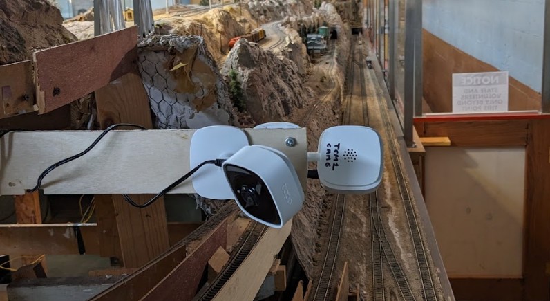
To that end, I’ve added 2 cameras in the back of the layout, pointed at the track:
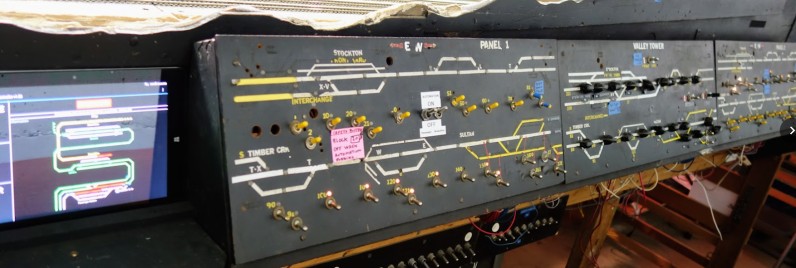
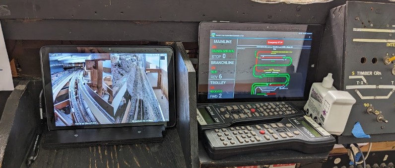
These cameras provide a video feed on the internal layout wifi which is then picked up by a new tablet display next to the Stockton Panel:
The tablet runs a special custom software that I wrote. It takes the video feed from both cameras and displays it side by side:
Click here to continue reading...
Affected |
Turnout T830 (Branchline after Angel Camps). |
Description |
Derailment due to gap, point not closing properly. |
Summary Fix |
Spiked in-place |
Started |
2024-07-29 |
Status |
Temporarily fixed. Turnout is still not functional. |
Description of Issue
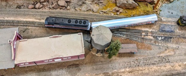
The branchline Amtrak train is a back-and-forth shuttle. It has been derailing in a rather unusual way lately on its way back to the station:
That’s a pretty unusual situation. The issue is not with the turnout as seen above, but the previous/following on at T830.
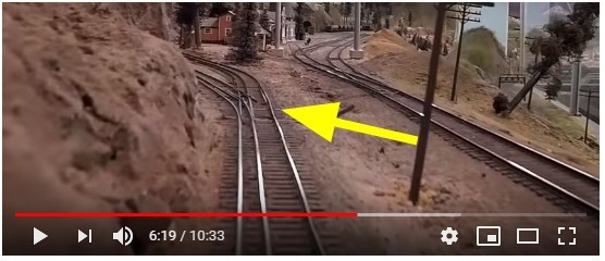
The branchline features complex dual-gauge turnout, being both standard gauge and narrow gauge. The single track splits into a siding at turnout T830 when arriving at Angel Camp. However the curved closure rail has been broken and missing on that particular turnout at least since 2015, even if not more -- which means the turnout is essentially unusable.
Screenshot of a 2015 cab ride video showing the broken point on T830.
Back in 2019, the throwbar on this turnout started shifting, and the gap was opening in the top switch rail -- engines or cars were derailing as they were mistakenly trying to take the diverging direction. I addressed that in 2019 by spiking the turnout throwbar. Apparently the issue started appearing again:
Click here to continue reading...
2024-07-29 - Branchline Power
Category RandallOrion and I are finalizing a project I had started in 2019: repower the entirety of the branchline and, more importantly, address the polarity reverser issue.
The branchline on the Randall layout essentially acts as a very long reverse loop and can be conceptualized as being composed of 3 parts:
- The most visible part of the Brancheline is the mountain section -- the branchline connects to the mainline at Sonora via turnouts T322 and T324. This part then goes through Angel Camp (B820), the Canyon (B830), and on the other side of the mountain onto Smith Flat (B840) and finally You Bet (B860). All this part of the Branchline is dual gauge.
- The second part of the branchline is the part most people don’t get to see as it serpentines through the unscenicked back of the layout. Of note, this section contains a small coal yard, which I understand was designed by Mr. Perry. On my track map, I designate this B870 up to B890.
- The third part of the branchline is where the end of B890 meets again the mainline just after the Stockton Station at what is called the “Rodgers’ Junction”.
Up to now, the entirety of the branchline was connected to the DCC power by a Lenz LK100 polarity reverser. Since the branchline is, by design, a reverse loop, it does make sense to have a polarity reverse. However that does not justify powering the entire route via the polarity reverser -- the issue is that polarity reversers work by detecting shorts, so essentially anything that shorts the branchline, anywhere on it, triggers the polarity reverser to try to “fix” the polarity.
A better design would be to rewire the branchline such that the dual-gauge section matches the polarity of the mainline at Sonora, that the B890 block at Rodgers matches the mainline at Rodgers, and some or all of the middle part be the polarity reverser section.
So that’s what Orion and I are attempting to finish. We’re partly done, yet some notable progress has been made.
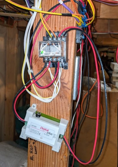
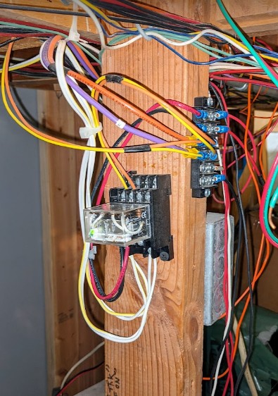
First, the polarity reverse is gone from the source DCC bus:
|
|
Explanation of the wiring above:
Click here to continue reading...
The latest post indicated how the Branchline Automation was failing due to an issue with the track sensors becoming flaky.
As a follow up, I changed some of the sensors, added a couple new ones, and even found the B830 block that I was missing before, albeit not how I expected it.
On the plus side, the automation now benefits from having a physical sensor for B830, which is the canyon bridge on the branchline.
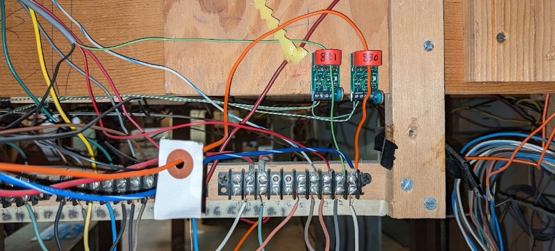
First I changed the “flaky” NCE BD20 sensor from block B821. I replaced it by a BD20 fitted with an adjustable potentiometer, hoping I could somewhat adjust the sensitivity better. And at the same time I found on the terminal block an orange wire directly feeding the B830 canyon block:
Well, that didn’t quite work as expected.
Click here to continue reading...
The Branchline Automation has been failing for a week or two now. It seems to start ok, then fails mid-morning. Symptom is that the train drives back in recovery mode, whilst it’s already on the parked block. As a one-sentence recap, one of the main design points of Conductor 2 is to have fancy recovery abilities in the automation script to be able to re-align the trains when they are not at their expected locations.
Checking the logs last week, I could not figure why it failed in the first place. Let’s try again.
After monitoring the train for a little while this morning, I got this:
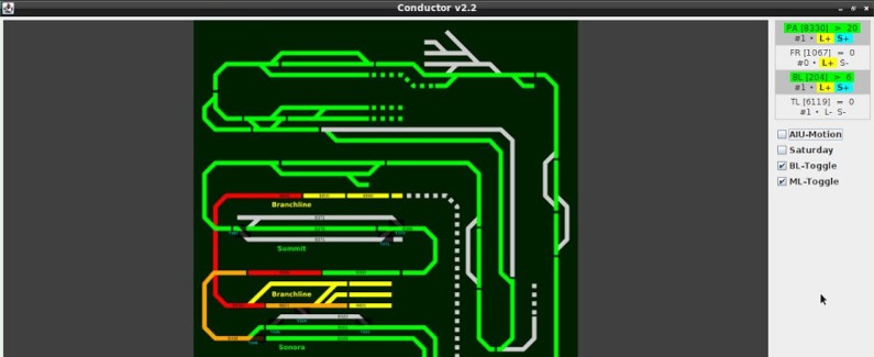
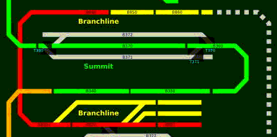
Thus the automation control sees 3 blocks occupied, whereas the train is visually stopped at the boundary between B820 (BL station) and B801 (BL parked). It goes without saying that only one block should be occupied here, or maybe 2 if the train is stopped at the boundary between 2 blocks.
Something interesting in this log… (Line starting with ⇒ are my annotations):
Click here to continue reading...
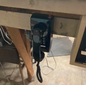
Orion is working on a project favorite of his: creating an internal intercom system for the Randall Museum Model Railroad.
When it was part of the GGMRC, the layout used to have a few phones connected together to a single phone landline. This project is not linked to that at all -- the landline is long gone.
The root of the project is that we have 2 yards on opposite sides of the layout, separated by a big mountain in between. If someone wants to enter the mainline from the back, it would be nice if they could talk to the operators in the front to warn them they are going to enter the mainline. Something other than yelling across the room -- which doesn’t work on a loud busy Saturday morning anyway.
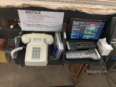
Thus the project is to create an internal-only “intercom” system with 3 phones connected to each other. Orion wants to use POTS wall phones, such as the one depicted on the left above, and use them unmodified.
To that order, he has installed some phone jacks and connected them all together.
My understanding is that he’s powering the phones by injecting 12 V DC on the line with a resistor. I need to double check and write the specs for this down here.
Overall the system now works -- both operators can pick up their phone and talk to each other.
What’s missing is making the phones ring. I suggested we simply simulate a ringer - an arduino with a speaker would be trivial to make that happen. Instead, Orion would like to stay true to his project and make the phones actually ring. Which would mean to introduce the proper ring signal on the phone line (90 V at 20 Hz). Challenge accepted? Sure. But that means what could have been accomplished in a few minutes is now going to take months whilst I research this. I did point out that was overdoing it, but then that’s his choice. As Voltaire said, le mieux est l'ennemi du bien.
https://pbxbook.com/other/trunks.html has some pretty good explanations of POTS signaling -- which is quite relevant because these terms have a railroad origin. I encourage you to read that site.
Unrelated anecdote: if you were in the US around 2005-2015, you would have heard of the Sprint Corporation -- they used to do landline phone and then cell phone before generating their own demise due to poor management. But more to the point is that SPRINT is a direct offset from the Southern Pacific attempt at using their track-side telegraph lines to compete with then-monopole ATT on long distance communications. See details on Wikipedia here.
Click here to continue reading...
UP 8330 is now the pulling mainline passenger train, replacing Walthers UP 8312:
You might recall UP 8330 has been its own little saga, and is now working fine after a motor swap (under Walthers’ warranty) and a brand new LokSound 5 decoder (out of pocket expense).
UP 8312 has been running nicely since February, yet I recently had issues where it would not stop when coming back to the station at the end of its run. The first time I found it on this stopped here on this dirty track spot:
Click here to continue reading...
Orion and I have completed fixing the ceiling light fixtures above the mountain. These fluorescent lights went off somewhere back in 2017 and were left unchanged because they are really hard to reach. This job has just been completed and it took about 3 hours to change the two fixtures:
Mountain-side Fluorescent Fixtures, before |
Mountain-side LED Fixtures, after |
The train room features fluorescent light fixtures which date from the 60s. They use old style ballasts, the kind filled with PCB, and some of them have leaked over the years. We already tried using Type A LED tubes in these and they won’t even work properly.
Back in 2023, I replaced one of the (somewhat) accessible light fixtures over Richmond Yard using one of the new-style “integrated” LED fixtures. This involves removing the entire old fixture. Instead, for the rest of the train room, I decided it would be easier to just do a fixture rewiring and use Type B (aka “Direct”) LED tubes, which would allow us to keep the existing fixtures in place. Orion was interested in learning more about that and do it, so I had him practice on the workbench using the old fixture from Richmond Yard, and once he got the hang of it, he did an in-place rewiring of the fixture in Lodi. That was a good learning experience and a great spot to do so because it’s easily accessible.
We had wanted to change the dead ones over the mountain for quite a while, but as you can see below, one challenge is getting in there and accessing the fixture:
For the new lights, I particularly like the GE Hybrid 32W QE T8 -- these can handle both Type A (ballast) and Type B (direct), and they have a physical color switch to fix them to the color temperature we want -- in this case 4100K.
Rewiring is actually a fairly easy job:
Click here to continue reading...
2024-05-31 - Valley Panel Tablet
Category RandallI’ve reinstalled the tablet by the Stockton Yard’s Valley Panel:
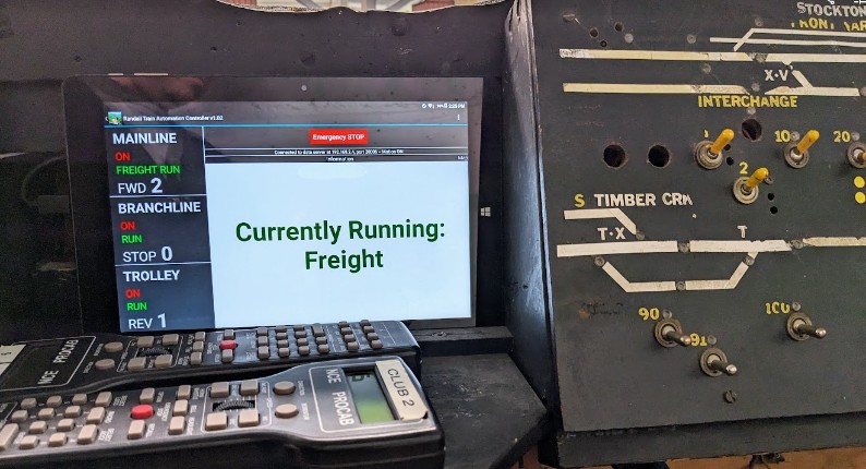
It had been out of commission for a while -- it wasn’t booting, that has been fixed. I also updated the RTAC software to work with the latest Conductor 2.
There’s a similar tablet in the front to show the currently running train to the public.
This one is for the Saturday Operators. They can see the state of the automation (whether it’s on, off, or in error), and when one swipes on the right pane, a map is displayed that shows the state of the track occupancy sensors:
Click here to continue reading...
